Download
1 / 18
330 likes | 599 Views
JK flip-flops. By: Travis Hoover 2/22/2011 CS 147 Dr. Lee. What is a JK Flip-flop?. A flip-flop is a circuit that has two stable states and can be used to store state information.

E N D
JK flip-flops By: Travis Hoover 2/22/2011 CS 147 Dr. Lee
What is a JK Flip-flop? • A flip-flop is a circuit that has two stable states and can be used to store state information. • The flip-flop can be made to change state by signals applied to one or more control inputs and will have one or two outputs.
JK Terminology/Structure Has 5 inputs named: J(set),K(reset), PR, CLR, and CLK Has 2 outputs: Q and Q’ PR = Preset CLR = Clear CLK = Clock Set: when it stores a binary 1 Cleared (reset): when it stores a binary 0
Outputs The Q output is the primary output. This means that the binary bit stored in the flip-flop, 1 or 0, is the same as Q. The Q’ output is the opposite binary bit value that is stored in Q. The PR and CLR inputs always override the J,K inputs.
Inputs: PR and CLR A low at the PR input sets Q = 1 A low at the CLR input sets Q = 0
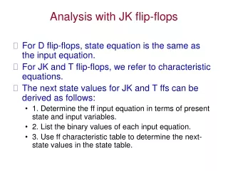
Inputs: J and K • The logic states applied to the J and K inputs cause the flip-flop to operate 4 different ways. • The way the logic state is applied to J and K is called Mode of Operation. • The mode of operation refers to the condition of the flip-flop as it prepares for the positive clock pulse.
Four Modes Of Operation The 4 modes of operation are: hold, set, reset, toggle JK contains an internal Active Low SR latch.
Active Low SR Latch Point to remember: A ‘0’ at the set or the reset will either set or reset the value of Q.
Review: Truth Table for NAND 2 Inputs: 3 Inputs:
Mode of Operation: Hold Hold: no change in Q.
Mode of Operation: Set Set: Q = 1.
Mode of Operation: Reset Reset: Q = 0.
Mode of Operation: Toggle Toggle: Q = Q’.
Mode of Operation: Toggle again Toggle: Q = Q’.
Characteristic Equation Characteristic Equation: Q(t+1) = J.Q’+ K’.Q
If only one slide to remember… Characteristic Equation: Q(t+1) = J.Q’+ K’.Q Q is the primary output. SR Latch: A ‘0’ at the set or the reset will either set or reset the value of Q.
More information / Questions? • http://www.wisc-online.com/objects/ViewObject.aspx?ID=DIG3303 • http://hyperphysics.phy-astr.gsu.edu/hbase/electronic/jkflipflop.html • http://computer.howstuffworks.com/boolean5.htm • http://www.youtube.com/watch?v=bN02shtPWuI