Download
1 / 38
380 likes | 507 Views
The Hall Current in Collisionless Reconnection and Reconnection in an Electron-Positron Plasma. Manfred Scholer. Max-Planck-Inst. Extraterrestrische Physik, Garching, Germany Queen MaryCollege, University London, UK. Claus H. Jaroschek Rudolf A. Treumann.

E N D
The Hall Current in Collisionless Reconnection and Reconnection in an Electron-Positron Plasma Manfred Scholer Max-Planck-Inst. Extraterrestrische Physik, Garching, Germany Queen MaryCollege, University London, UK Claus H. Jaroschek Rudolf A. Treumann
Hall physics and the importance for collisionless reconnection • 2. Onset of reconnection in thin current sheets (PIC simulations) • PIC simulations of collisionless reconnection in an electron – positron • plasma and particle acceleration • Recent PIC simulations of reconnection in large systems • (Daughton et al.)
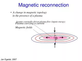
Sweet-Parker Reconnection Mass conservation Energy conservation Ohm‘s+Ampere‘s law
Sweet-Parker reconnection rate is magnetic Reynolds number (Lundquist number) L is of ambient system size and h small: Sweet/Parker rate is very small
Petschek Reconnection Petschek reconnection rate Because of logarithmic dependence on Rm Petschek rate is much larger
Schematic of Hall Current Systen in Reconnection Outer circle is the ion inertial domain. Inner circle (light blue) is the electron inertial region. Red arrows indicateinflow (of electrons) and reconnection jet outflow. Ions are unmagnetized on the ion inertial scale. Thin blue arrows are the Hall currents which generate quadrupolar Hall magnetic field.
Two-Fluid-Simulation (left) and Cluster Observations (right) of Reconnection on Ion Scale Vaivads et al., PRL 2004 Reconnecting B-component Out-of-plane B-component Normal B-component Spaceraft configuration Color-coded is out-of-plane magnetic field component (2D two-fluid simulation)
Geospace Environmental Modeling Reconnection Challenge Results Dissipation region of the order of the electron skin depth and thus much smaller than the ion inertial length At this distance the Hall term in Ohm‘s law becomes important and introduces dispersion Below ions and electrons decouple. Electrons are frozen in. Whistler waves (and not nondispersive Alfven waves) control dynamics Electron frozen in condition boken at Electric field at X line supported by nongyrotropic electron pressure or electron inertia Hall term whistler waves Electron inertia Scales
Why is Wave Dispersion Important? Quadratic dispersion of whistler wave Smaller scales have higher velocities Electron diffusion region or since Shay and Drake, GRLett 1998
Shay and Drake, GRLett 1998 Reconnection is independent of d and therefore of the mechanism by which the electron frozen in condition is broken (no bottleneck on electron scale) When electron diffusion region of order of electron inertial scale de (skin depth) electron outflow velocity is of order of electron Alfven velocity (Ion) Alfven velocity and length of ion diffusion region determines reconnection rate. 2-D fluid, hybrid, and PIC simulations show that length of ion diffusion region is about 10 di (ion inertial length). Thus reconnection rate (inflow velocity) is about 0.1 vA (Claim of universal reconnection rate)
GEM Result – Reconnection Rate in Various Numerical Simulations Birn et al., JGR 2001 2-D Simulation - current sheet with anti-parallel magnetic field. In GEM challenge initial reconnection is enforced at by superposition of magnetic field disturbance Reconnection rate is slope of reconnected flux vs time Reconnection rate independent of dissipation mechanism. Whistler phase speed limits outflow speed. When diffusion region has electron scale the outflow velocity should be whistler speed based on electron skin depth = electron Alfven speed. MHD reconnection is too slow by orders of magnitude
Classification of Computer Simulation Models of Plasmas Kinetic Description Fluid Description Full particle codes PIC Vlasov Codes 2 Fluid MHD Code MHD Code Hybrid Code Finite mass electron fluid Electrons massless fluid Reconnection electric field supported by either electron inertia or pressure tensor Reconnection simulations need an artificial resistivity
PIC Simulation Industry Bhattacharjee, ………, Univ. New Hampshire Büchner,…., MPI Lindau, Germany Daughton, Scudder, Karimabadi, Univ. Iowa, UC San Diego Drake, Sitnov, Swisdak, Shay, Univ. Maryland Grauer, Schmitz,…, Univ. Bochum, Germany Hesse, Kutzentsova, Winske, NASA Goddard, Los Alamos Natl. Lab. Horiuchi, Pei, Sato, Kyoto Univ., Japan Hoshino, Shinohara, Fujimoto, ..,Tokyo Univ., ISAS, Tokyo Inst. Techn., Japan Lapenta, Brackbill, Ricci, Los Alamos Natl. Lab. Pritchett, Coroniti, UCLA (MPI Garching)
3-D Full Particle Simulations (PIC) of Reconnection Investigate reconnection onset Double Harris-sheet Current sheet width = 1 ion inertial length Periodicity in all three directions particles of each species 3-D Particle-in-Cell code (relativistic): Multigrid algorithm for Poisson equation massively parallel
Thin Current Sheet with Antiparallel Magnetic Field Explosive reconnection within a few ion times! Right: Reconnected flux versus time. The whole flux between the two current sheets is reconnected when Left: Magnetic field pattern at four different times (Isointensity contours of Scholer et al., Phys. Plasmas 2004
Lower Hybrid Drift Instability at the Current Sheet Edge Color coded electron density (left) and electric field (right) in the current directionin the plane perpendicular to the magnetic field. z is in the current direction – perp to magnetic field
Cuts of Various Parameters BEFORE Reconnection Starts t=0 t=4 Cuts of electron contribution to current density (top) and electron density across the current sheet. Profiles at t=0 are shown dashed for reference. Reduced electron distribution function f(v_z) verusus v_z in the current sheet gradient region (top) and in the center (bottom) of the current sheet exhibiting electron acceleration in the electric field of the LHD waves.
Thin Current Sheet with Antiparallel Field plus Guide Field (Sheared Field Configuration) B = 1 z In the guide field case the LHDI develops as well, but it takes considerbly longer time for reconnection to set in. After reconnection onset the reconnection rate is about the same as in the exactly antiparallel case.
Jaroschek et al., Phys. Plasmas 2004 Reconnection in a Pair Plasma: 2-D and 3-D Full Particle Simulations • Pair dominance in plasma of • Relativistic extragalactic jets • Pulsar outflows (Crab) • c) Core of AGN‘s Simulation: Initial state: 1-D curent sheet, relativistic Maxwell-Juettner plasma (100 keV) Reconnection initialized by disturbance in center of current sheet Parameters: current sheet width (1 – 2 inertial lengths do) c / vAo between 1 and Ö2 in a 3-D run about 2 x 10⁹ particles
Reconnection rate after onset phase (electric field along X line) (E > 0.2) Ez n Ez Current sheet and quasi-static acceleration region begin to sparate X-line at early times
Multiple X line and island coalescence phase Schematic of field topology Field lines Ez Particle acceleration (g) along center line y y g x
Temporal development 0 ton tcoa tsep tequ Island coalescence Separation of X lines along current sheet Single X line X line buildup 80 140 t wc = 40
Temporal development of the distribution function in the 2-D run
More (2-D) PIC Simulations of Reconnection in an Electron-Positron Plasma (From Bessho and Bhattacharjee, PRL 2005)
Reconnection rate Bessho and Bhattajarchee: High reconnection rate in pair plasma (E > 0.2) Note: there is no Hall current in a pair plasma!
Results from a 3-D PIC Simulation Ez /B y x Acceleration region about 20 electron inertial lengths in current direction (z). Limits g to 30. Ez z Fast onset of relativistic drift kink instability due to RTSI x Heating by a relativistic Buneman-type Instability (RTSI) z vz density Trapping x z
Application to Pair-Dominated Active Galactic Nucleus Core Regions (Extremely hard radio spectra, Power output of P ~ 1047 ergs/sec) Jaroschek et al., ApJ Lett. 2004 Total spectral synchrotron output as a function of w / wco (wco = cyclotron frequency) Model assuming stochastic distribution of reconnection zones over the entire coronal souce region can explain power output and spectra
There is no Hall current system in a pair plasma, • yet reconnection is fast • Is Hall physics really the key mechanism for fast reconnection • in an electron – proton plasma?
Large Scale PIC Simulation of Reconnection (Electron-Proton Plasma) Daughton et al. Phys. Plasmas 2006 Island formation Extent of electron diffusion region > 10 di
Daughton et al.: The results are not consistent with the standard model of Hall mediated fast reconnection. Fast reconnection may still be possible so long as the process for generating secondary islands remains vigorous…
Hybrid Simulation of Tail Reconnection Arzner and Scholer, JGR 2001 By – field (out-of-plane) y-component of ion vorticity is frozen into ion fluid u. In the inflow region both terms are zero. Occurrence of vorticity has to be cancelled by By
Summary Reconnection in a pair plasma (no Hall physics involved) is fast In the late phase reconnection in a pair plasma is violent and particles are accelerated to high energies (>30 g, also in 3-D) PIC simulations of (undriven) reconnection in an electron – proton plasma in a long system show that the electron diffusion region becomes very large, more than 10 ion inertial lengths long Hybrid simulations (massless electrons) with a large (resistive) diffusion region exhibit quadrupolar (Hall-type) magnetic fields. (Hall magnetic fields may only tell us that the plasma is collisionless)
Physics of collisionless reconnection continues to be an open question
PIC Simulations of Reconnection – Electron Acceleration (Large Guide-Field Simulation) Electron holes Electron distibution at three times Stong parallel electric fields Drake et al., PRL 2005
2-D PIC Simulations of Reconnection – Electron Acceleration by Surfing (Strongly driven inflow) Ez polarization electric field near sepatarix Electric force can balance Lorentz force Electron stays there and gains energy by moving in the y direction Hoshino, JGR 2005
Acceleration in Contracting Magnetic Islands Drake et al. Nature 2006 Test particle simulation of electron Fermi acceleration in squashed flux bubbles PIC reconnection simulation producing magnetic islands