Download
1 / 71
710 likes | 872 Views
Skeletons and Skinning. Bones and Skeletons Mesh Skinning Chapter 17 in the textbook. Skeletal Animation. Victoria. Skeletons. Skeleton : a pose-able framework of joints arranged in a tree structure. An invisible armature to manipulate the skin and other geometric data of the character

E N D
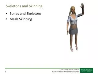
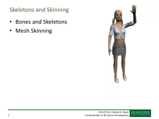
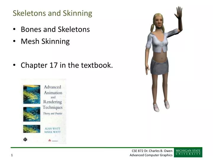
Skeletons and Skinning • Bones and Skeletons • Mesh Skinning • Chapter 17 in the textbook.
Skeletal Animation Victoria
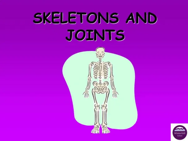
Skeletons • Skeleton: a pose-able framework of joints arranged in a tree structure. An invisible armature to manipulate the skin and other geometric data of the character • Joint: allows relative movement within the skeleton. Joints are equivalent to 4x4 matrix transformations. • Usually defined as an offset and rotation independently • Bone: what’s the difference between a joint and a bone? • Sometimes includes a length or actual geometry
DOFs • Degree of Freedom (DOF): A variable φ describing a particular axis or dimension of movement within a joint • Joints typically have around 1-6 DOFs (φ1…φN) Can have more (up to 9 for affine) • Changing the DOF values over time results in the animation of the skeleton • Rigid body transformations: 6DOF • Arbitrary rotations: 3DOF
Joints • Core Joint Data • DOFs (N floats) • Base pose information • Additional Data • Joint offset vector: r • DOF limits (min & max value per DOF) • Type-specific data (rotation/translation axes, constants…) • Tree data (pointers to children, siblings, parent…)
Skeleton Posing Process • Specify DOF values for the skeleton • Traverse the hierarchy using forward kinematics to compute the world matrices • Use world matrices to deform skin & render The matrices can also be used for other things such as collision detection, FX, etc.
Forward Kinematics • Each joint computes a local matrix M based on the DOFs and some formula representative of the joint type: Local matrix M = Mjoint(φ1,φ2,…,φN) • Then, world matrix W is computed by concatenating M with the world matrix of the parent joint World matrix W = WparentM
Offset Vectors for Joints • It is convenient to have a 3D offset vector r for every joint which represents its pivot point relative to its parent’s matrix • r = <tx, ty, tz>
Rotation • Usually implemented as a Quaternions • Matricies can’t be interpolated easily, Quaternions can… Ultimately it’s a matrix. We sometimes also have Euler angles. Sometime we have all three.
Quaternions Quaterions are one of the most powerful ways to represent rotation They will seem almost magical in what they do
The basic idea Imaginary Complex numbers can represent 2D rotation (a,b) q Real This is a completely made up mathematical concept, but it turns out to be very useful. It can represent angles with no trig functions.
Complex Number advantages Imaginary A normalized complex number uniquely represents a rotation Multiplying two complex numbers together add the rotation angles. So, make q into a complex number cq and w into a complex number cw cqcw = cq+w (a,b) q Real Normalizing a complex number. Just like normalizing a vector.
Can we extend this to 3D? Why do we care? Complex numbers represent rotation in a form that can be easily multiplied together with simple multiplication and division operations. We’d love to be able to do that in 3D with something smaller than a matrix. You can compose a rotation and orientation with a single multiplication. Well, we have real and imaginary. Could we have even more imaginary? Yes, we can! William Rowan Hamilton invented quaternions in 1843 which provide a tool for rotation that easily composes and interpolates. We’ll use them a lot.
Quaternion Plaque on Broom Bridge in Dublin, Ireland Here as he walked by on the 16th of October 1843 Sir William Rowan Hamilton in a flash of genius discovered the fundamental formula for quaternion multiplication i2=j2=k2=ijk= -1 & cut it on a stone of this bridge
The main idea A unit quaternion: Think of them as 4 element vectors. To make a unit quaternion, you simply divide by the length of the vector. This is Normalizing just as in 2D and 3D vectors.
How much do we really need to know? • A quaternion represents a rotation. • q1 * q2 represent rotation q2 followed by rotation q1. • q and –q are the same rotation. • A multiplication rule exists (you can look it up) Let (x, y, z) be a normalized vector and q an angle Is a rotation around (x,y,z) by q radians Quaterion inverse:
Creating a Quaternion You’re given a Vector v and an angle to rotate around that vector of q. The quaternion to do that will be: publicstaticQuaternionCreateFromAxisAngle(Vector3 axis, float angle) { Quaternionquaternion; floatnum2 = angle * 0.5f; floatnum = (float) Math.Sin((double) num2); floatnum3 = (float) Math.Cos((double) num2); quaternion.X = axis.X * num; quaternion.Y = axis.Y * num; quaternion.Z = axis.Z * num; quaternion.W = num3; return quaternion; }
Composing Quaternions Quaternion q = Quaternion.CreateFromAxisAngle(new Vector3(0, 0, 1), rx) * Quaternion.CreateFromAxisAngle(new Vector3(0, 1, 0), ry) * Quaternion.CreateFromAxisAngle(new Vector3(1, 0, 0), rx); Important: Operations read right to left, not left to right!
Quaternion to Rotation Matrix Other way is messy
Negation Characteristics • q and –q correspond to the same orientation • Why?
Dot Product Characteristic • Dot product is cos of ½ angle between orientations
Quaterion Interpolation One of the main reasons quaternions are so popular is that they are easy to interpolate. They are very commonly used for orientation keyframes and skeletal animation.
Slerp for Quaternions Slerp is “spherical linear interpolation” Dot product is the cosine of ½ the angle between orientations (important difference) q above is ½ of the angle If cosine is < 0, the angle is greater than 180 degrees…
Perfect Rotations Slerp with two quaternions will rotate from one orientation to another using a uniform angular velocity and a fixed rotation axis.
Going the long way around… There’s always two possible rotations: the short way and the long way. If the cos(q) < 0, where q is the angle between the quaternions (not the angle between the orientations), we are going the long way around. If that happens, then instead of doing Slerp(q1, q2, t), so Slerp(q1, -q2, t). Negating one quaternion will force the other path.
Quaternion Advantages/Disadvantages Advantages Compact notation Composes with simple multiplication Very efficient and fast Interpolates perfectly with slerp! Perfect for keyframe animation Disadvantages Not unique: q and –q are the same rotation and there are other redundancies. 4 values to represent 3 things – some redundancy.
DOF Limits • DOF is often range limited • Elbow could be limited from 0º to 150º
Skeleton Rigging • Skeleton Rigging – Setting up the skeleton for a figure • Bones • Joints • DOF’s • Limits
Poses • Adjust DOFs to specify the pose of the skeleton • We can define a pose Φ more formally as a vector of N numbers that maps to a set of DOFs in the skeleton Φ = [φ1 φ2 … φN]
Rotational Hinge: 1-DOF Universal: 2-DOF Around two axis Ball & Socket: 3-DOF Euler Angles Quaternions Translational Prismatic: 1-DOF Translational: 3-DOF (or any number) Compound Free Screw Constraint Etc. Non-Rigid Scale Shear Etc. Design your own... Joint Types
Rigid Parts • Robots and mechanical creatures • Rigid parts, no smooth skin • Each part is transformed by its joint matrix • Every vertex of the character’s geometry is transformed by exactly one matrix where v is defined in joint’s local space
Mathematics of mesh skinning Where: is the number of matrices. is the vertex position. is the weight associated. is the transformation matrix. with
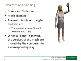
Smooth Skin • A vertex can be attached to more than one joint/bone with adjustable weights that control how much each joint affects it • Rarely more than 4 • Result is a blending of the n transformations • Algorithm names • blended skin, skeletal subspace deformation (SSD), multi-matrix skin, matrix palette skinning…
Bone offset method/Vertex offset method • What space should be vertices be in? • If in world coordinates (usually the starting place), M for each bone must be deformation from original structure • Vertex offset method • What if vertices defined relative to bones • (which bone?) generally this is not used. • M is now joint manipulation relative to parent • Bone offset method
Mesh skinning with binding matrices Bi is the local to world transform for bone i before we move it (the base pose) Mi is the local to world transform for bone i moved wi is the bone weight for the vertex v is the vertex before we move it v’ is the vertex after we deform The same operations are done on the vertex normal, but it has to be renormalized when we are done.
Normals • Normals must also be transformed • Options • Recompute normals • Do only the rotation of existing normals • Normals are also blended. But, we MUST renormalize!
Easy Muscles & Other Effects • Use additional joints for muscle bulges • The bicep could be a translational or scaling joint that smoothly controls some of the vertices in the upper arm. • Fun with: • muscles, fat bulges, facial expressions, simple clothing
Limitations of Smooth Skin • Smooth skin is very simple and quite fast, but its quality is limited • Joints tend to collapse as they bend more • Very difficult to get specific control • Unintuitive and difficult to edit • Still, it is common in games and commercial animation! • If nothing else, it is a good baseline upon which more complex schemes can be built
Bone Links • Bone links are extra joints inserted in the skeleton to assist with the skinning • Instead of one joint, an elbow may be 2-3 joints • Allows each joint to limit the bend angle! • Why does this help?
Shape Interpolation • An option is to model vertex positions at points in the motion • Interpolate between the positions • More up-front design, but better appearance • Model an elbow straight and fully bent • Use DOF to determine vertex position, then do the skinning.
Skin Binding • Skin binding consists of assigning the vertex weights • Binding algorithms typically involve heuristic approaches • Any ideas?
Containment Binding • Volume primitives around the bones • Boxes, cylinders, etc. • Vertex weights assigned based on which primitives it is in
Point-to-Line Mapping • Which bone is a vertex nearest? • How do we decide to attach to more than one bone/joint?
Delaunay Tetrahedralization • A tetrahedralization of the volume within the skin • The tetrahedra connect all of the skin verts and joint pivot points in a ‘Delaunay’ fashion • Basically segments the vertices • How can we get weights?
Skin Adjustment • Mesh Smoothing: Joints attached rigidly, then weights adjusted for smoothness. • Weight Painting: Indicate weights as colors. • Direct Manipulation: Bend the joint, then drag vertices where they should be. From this, automatically calculate the weight (least squares estimate).