Download
1 / 23
230 likes | 333 Views
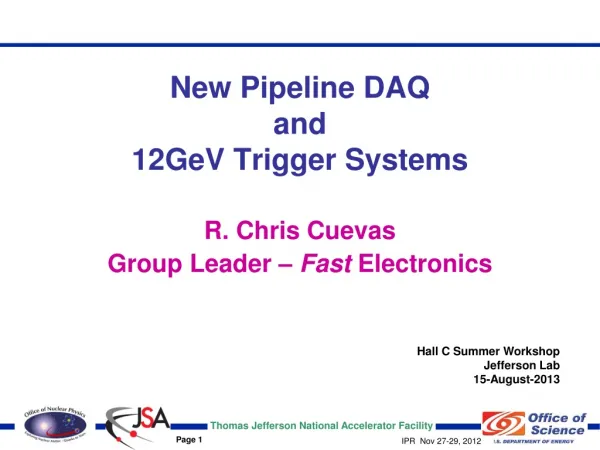
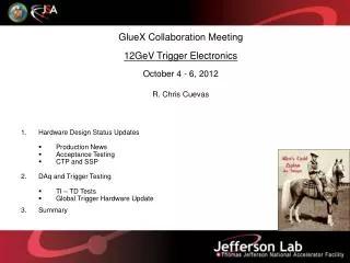
GlueX Collaboration Meeting October 3 - 5, 2013 12GeV Trigger Electronics R. Chris Cuevas . Hardware Status Production Updates DAq and Trigger Testing Global Trigger Hardware Testing Implementation Plans Summary . All Trigger Modules Delivered! . SSP. FADC250. CTP. SSP. GTP.

E N D
GlueX Collaboration Meeting October 3 - 5, 2013 12GeV Trigger Electronics R. Chris Cuevas • Hardware Status • Production Updates • DAq and Trigger Testing • Global Trigger Hardware Testing • Implementation Plans • Summary
All Trigger Modules Delivered! SSP FADC250 CTP SSP GTP L1 Trigger ‘Data’ MTP Ribbon Fiber • Global Trigger Crate • Sub-System Processor • Global Trigger Processor SD TI TD Trigger ‘Link” Control Clock, Sync MTP Ribbon Fiber TS • Front End Crate • FADC250, (FADC125), (F1TDC) • Crate Trigger Processor • Signal Distribution • Trigger Interface • Trigger Control/Synchronization • Trigger Supervisor • Trigger Distribution 2
William Gu Trigger Hardware Status • Trigger Supervisor ( TS ) (FY-11/12/13 activity) • Boards have been thoroughly tested and delivered • Revisions to firmware are minor iterations are a result of testing improvements • Production boards are being used in Global Test Stand for a variety of verification testing of firmware and CODA libraries. • Functional hardware verification with Trigger Distribution(TD) boards complete. • TS Rear Transition Module (TSIO) are assembled and tested. Fully functional with production GTP cable interface. (Next page photo) • Receives 32 Trigger ‘Bits’ from GTP via high speed LVPECL cables • Global precision clock distributed to SD on VXS backplane to TD cards • Synchronization and Trigger Word distributed to crate Trigger Interface boards via parallel fiber • Manages global crate triggers and ReadOut Controller events 3
Trigger Hardware Status - TS W. Gu DAQ Group GTP Global Trigger Crate Xilinx VirtexV LX30T-FG665 Optional QSFP Fiber External I/O (trg, clk…) 32 LVPECL Trigger ‘Bits’ Four Cables 8 Bits each VXS P0 Global Clock SYNC Trig1, Trig2 4
William Gu Trigger Hardware Status • TI – TDTrigger Interface – Trigger Distribution • All production modules have been delivered and pass acceptance • 10 TI boards have been modified to be used as TI-”Master” units • - TI “Master” mode will allow up to 9 front end crates to be operated from a single TI. Perfect application for several sub-systems. • The TI Master boards have been modified and tested thoroughly. • TD boards have been installed in Hall D CH for several months and are being used for multi-crate DAQ testing. • Acceptance test routine development will be used for long term maintenance • Software (CODA) library routines are undergoing minor iterations to keep up with minor firmware changes. • Remote firmware download feature is complete. 5
GLOBALTRIGGERPROCESSOR S. Kaneta B. Raydo Gigabit Links to SSP VXS “Switch” card • 2 Production Boards • delivered • Passed acceptance testing • Production design includes: • QSFP fiber port • Front panel I/O • Front panel RJ45 Ethernet • 1Gb Ethernet • Significant testing with • full VXS crate. All Gigabit • Links work as expected. DDR2 Memory 256 MB Altera FPGA Stratix IV GX 4 Channel QSFP Fiber 4x 8-Channel LVPECL Trigger Outputs to TS High Speed Densi-Shield® Cable assemblies RJ45 Ethernet Jack JTAG 6
Scott Kaneta Ben Raydo Chris Hewitt Trigger Hardware Status • Global Trigger Processor ( GTP ) (FY – 13) • 2 Production GTP modules have been fabricated, assembled and tested thoroughly in Global Test Stand. • Interface requirements to SSP and TS have been finalized and tested • The GTP transceivers (Altera) have been tested with the SSP at 5Gb/s. • GTP Firmware and hardware verification has taken advantage of the CLAS12 Drift Chamber Tracking Trigger application. • – Full drift chamber detector is read out with a full crate • -- All GTP Gigabit serial lanes tested in this fashion • -- Timing and alignment of VXS trigger data is tested with working DC system • -- FPGA resource testing exceeds expected resources needed for Hall D • Firmware development and verification activities: • Ethernet interface implemented successfully • -- GUI interface uses Root • Embedded processor development in progress for Hall D applications to manage Global Trigger equations and Global Trigger monitoring. Will use Altera NIOS processor to run Linux. 7
Ben Raydo Sub-System Processor Status VME64x ‘P1’ VME64x ‘P2’ VXS ‘P0’ Xilinx Virtex V ‘TX150T 8 QSFP Fiber Transceivers From 8 Front End Crate CTP 8 8
Trigger Hardware Status Ben Raydo • SubSystemProcessor ( SSP ) • All production boards have been delivered. • Production contract included: • 10 Hall D • 15 Hall B • 1 each for Halls A & C • Acceptance testing is complete and Ben’s test code will be retained for long term maintenance/development. • New FO Transceivers (QSFP) on production boards • VME firmware update feature is complete • Monitoring functions include: • Counters (Scaler) for Input/Output signals • Hall D specific pulse integral histograms • SerDes bit errors, Data waveform capture from Optic transceivers • Manages trigger information from up to 8 front end crates. • (2048 channels!) • SSP applications are beginning to blossom and these units will be used for a variety of DAq and Trigger solutions. (MicroMegas, RICH) 9
Crate Trigger Processor Hai Dong Jeff Wilson • Crate Trigger Processor ( CTP ) • Production quantities (33) awarded to MTEQ in Virginia. (30 for Hall D) • 1st Article board passes acceptance testing! • - Production boards expected delivery 22July2013 • - Final board delivered 23Sept2013 • - Delay because of circuit board • yield issues • 20 of 33 boards pass acceptance testing • Minor assembly corrections needed for 13 • Full Crate Acceptance Testing has started • So far no issues with FCAT • Remote firmware download feature • needs final test • CTP boards will be delivered to Hall groups after FCAT is completed New Front Panel I/O MTP Parallel Optics 8 Gbps to SSP VXS Connectors Collect serial data from 16 FADC-250 (64Gbps) 2013 Production CTP 10
Crate Trigger Processor Hai Dong Jeff Wilson Somov Moffit • Hall D L1 trigger algorithm for full crate energy sum is stable and is part of FCAT • FCAT verifies that trigger data is aligned properly from all 16 FADC250 boards • High trigger rate tested in FCAT to excess of 135 KHz • All Gigabit serial lanes operated in sync @2.5Gbps • Clock counters, trigger counters on all boards verified to be in agreement • Production version will support higher serial speeds. (5Gbps per ’lane’) Matches V5-FX70T on FADC250, and cost for highest grade Virtex V FPGA is included on production boards. • Firmware iterations will be needed as minor features added to the CTP • Examples: - CTP to SSP link status information may need to be added • - Forward Error Correction for possible bit errors • Production version will include VXS connection to CPU slot (PPT-17) for development of PCIe interface if needed. Present control/monitoring is via I^2C through Trigger Interface. • - Lower priority and ROCs will have VXS (P0) connection • Level 1 algorithm requirements for Tagger hit pattern has been documented • New ‘scaler’ register requirements have been defined • TOF and Pair Spectrometer algorithm requirements have been discussed 11
Nick Nganga Trigger Hardware Status • Signal Distribution ( SD ) • All production modules have been delivered and passed acceptance! • Nick Nganga has updated the final firmware to include: • Remote FPGA firmware download Complete • Serial Number storage Complete • Recent firmware update for F1TDC test purposes Complete • Acceptance test routine development will be used for long term maintenance • Software (CODA) library routines complete and included with Full Crate Acceptance Testing (FCAT) – Bryan Moffit • SD provides precision low jitter fan-out of 250MHz system clock, trigger and synch signals over VXS backplane to VXS payload modules • Latest SD version includes clock jitter attenuation PLL • Successfully used 2 SD boards during HPS experiment 12
F. Barbosa H. Dong E. Jastrzembski Jeff Wilson Trigger Hardware Status • Flash ADC 250Msps ( FADC250 ) • - See Fernando’s update • Production board delivery to JLAB groups is complete • Production board repairs are progressing • “Mode 6” Firmware is undergoing modification after issues surfaced when testing this feature with Hall B PCAL detector. • - Hai and Ed are busy with other production board projects • Readout data includes pulse integral value and time stamp value is high resolution (LSB=62.5ps; 6-bits) • This mode will be used for production Physics operations and will be required for maximum trigger rate • Firmware revisions are stable now, and Bryan Moffit has created a DAQ site that will hold the latest User Guides for the DAQ and Trigger modules. • https://coda.jlab.org/wiki/index.php/JLab_Module_Manuals • Major firmware revisions unlikely but every firmware change requires software driver routines to be updated. • Will establish firmware change request method and prioritize firmware updates. (FE and DAQ groups) 13
Scott Kaneta Ben Raydo William Gu B. Moffit Global Crate Testing - Update • Scott has separated from the lab, • Fortunately though, the GTP hardware is • functioning as specified. • Cables from GTP to TS have been received and tested. • Densi-shield 8 pair x 4 • 32 Trigger ‘bits’ NOT serialized to eliminate latency. • SSPGTPTSTD TI • Full trigger system latency is OK • SSP GTP VXS Gigabit transmission • tested • GTP TS interface tested • Trigger equation development • Develop GTP Ethernet User Interface • The next step is to move the Global Trigger boards to the Hall D CH to continue testing with full front end crates and CTP. Will continue to iterate firmware and CODA libraries. 2.954us Measured full ‘round trip’ trigger latency 14
Specification Status • VXS and VME64x powered card enclosures • ALL crates for ALL Halls: Complete • -- One backplane replaced. 2 DIN connectors reversed! • -- Power supplies will need response time modification • Excessive PS ripple occurs with full crates • ‘Most’ crates have been modified • Trigger System Fiber Optics (Q1 – FY14 procurement) • System diagrams have updated for Hall D • Recent visit to the Hall shows cable tray installation beginning • Trigger racks in the Hall need to be installed • MTP fiber patch panels and patch cables received for Halls D, B, and C. • Final Trigger Fiber trunk lengths for Hall D & B contingent on cable tray installation • Procurement started. Custom cable so lengths are critical. May make sense to buy these trunk lines and install with JLAB labor. We have the test hardware to verify fibers after installation. 15
Summary • ALL 12GeV Trigger Modules have been delivered! • Firmware, firmware, firmware, will be iterated and require test verification for: • Tagger “Hit Count” algorithm, TOF, and Pair Spectrometer applications • SSP and GTP Global Trigger functions • Final TS firmware/functions • Production CTP are being fully qualified with FCAT • Issues with CTP that have not passed acceptance testing have been identified • Boards sent to contract assembler for rework • Production GTP are being tested and operated with full detector crate. (Hall B) • Prepared to move Global Trigger boards to Hall D CH for further testing and to identify any new functions that need to be added. • Acceptance testing activities are complete for delivered production boards. • Essential CODA library development has been completed • Check out 12GeV Trigger hardware progress: https://halldweb1.jlab.org/wiki/index.php/Electronics_Trigger_Meetings • Beam around the corner! Hot CheckOut in progress,, 16
Backup Slides All sorts of cool stuff
TI operating in TS mode William Gu • Trigger Interface module • can be configured to control • up to 9 front end crates • This method allows for • local control of a detector • Sub-system. • TI needs to be configured • for this mode with • multiple FO Transceivers • Local control of CLOCK, • SYNC, and Trigger signals • Global Trigger system • signals NOT available • Perfect for initial testing of • Detector sub-systems. • (FCAL, BCAL) TI-1 User Input/Output Front Panel (dECL) Fiber TI-2 TI-3 TI-4 TI-5 TI-6 TI-7 TI-8 TI-9 5
Bryan Moffit Et al. Full DAq Crate Testing Plans • Before deploying full crates with all required modules: • Will test using “Playback” mode and CODA • No input cables necessary; User defined signals loaded in front-end FPGA • Deterministic test for all channels and Gigabit serial lane alignment check • Verify TI SD Payload Board Synchronization and Clock • Re-Use these tools for Hall commissioning effort • Test station used for FINAL firmware verification and software ‘library’ development • Bryan Moffit has created a preliminary plan and list of test functions • See wiki link https://halldweb1.jlab.org/wiki/index.php/Full_Crate_Acceptance This full crate test station in EEL109 is an essential infrastructure element needed to test and verify the front end and trigger hardware/software before installation in the Halls. 17
System Description TS -> TD -> TI Link 1.25Gb/s Bi-Directional BUSY Trigger Sync Trig_Comnd CTP -> SSP -> GTP L1 Trig_Data Uni_Directional Energy Sums Trigger Supervisor (Distribution) Global Trigger Processing Sub-System Processing(Multi-Crate) Crate Trigger Processing Flash ADC Modules Detector Signals 6
CniPol Meeting Noise in the FADC (No Readout during data taking) Single Event All Events
CniPol Meeting Noise in the FADC (Readout during data taking) Single Event All Events
Two DAQ Crate Testing: FY11 • Pre-Production and 1st article • boards have been received and tested • Significant effort for circuit board • fabrication, assembly and acceptance • testing • System testing includes: • Gigabit serial data alignment • 4Gb/s from each slot • 64Gb/s to switch slot • Crate sum to Global crate @8Gb/s • Low jitter clock, synchronization • ~1.5ps clock jitter at crate level • 4ns Synchronization • Trigger rate testing • Readout Data rate testing • Bit-Error-Rate testing • -Need long term test (24 - 48 hrs) • Overall Trigger Signal Latency • ~2.3us (Without GTP and TS) 200KHz Trigger Rate! Readout Controller Capable of 110MB/s - Testing shows we are well within limits