Download

1 / 43
470 likes | 737 Views
ADMINISTRATION BUILDING. Justin Purcell Structural Option Advisor: Dr. Hanagan. PRESENTATION OUTLINE. Building Background Existing Structural System Proposal Proposed Structural System Cost and Schedule Analysis Electrical Redesign Conclusions Questions and Comments.

E N D
ADMINISTRATION BUILDING Justin Purcell Structural Option Advisor: Dr. Hanagan
PRESENTATION OUTLINE Building Background Existing Structural System Proposal Proposed Structural System Cost and Schedule Analysis Electrical Redesign Conclusions Questions and Comments
BUILDING INFORMATION Owner: Confidential Client Location: Pennsylvania Building Type: Office and Specialty Amenity Spaces Size: 311,905 S.F. Stories: 5/4 Above Grade F-F Height: 20’ For Ground Floor, 13.33’ For Floors 1-5 Building Height: 87’ Construction Dates: 10/22/01-7/24/03
KEY PLAYERS Architect: KlingStubbins CM: Skanska Engineer: KlingStubbins
GRAVITY SYSTEM • 3 ¼” Lightweight Concrete Slab, 4,000 PSI Concrete Strength • 3” Composite Metal Deck • W18x35 Composite Beams-40’ • W18x35 Composite Girders-20’ • W12x96 Columns-13.33’
LATERAL SYSTEM • Braced Frames (Frames in Red) • HSS 8x6x½ Braces • Coordinated With Mechanical Distribution
GOALS • Change Existing Structural System To A One-Way Slab, CIP Concrete System • Estimate Cost Of Existing And Proposed Structural System • Estimate Schedule Of Both Systems • Redesign Electrical System To Limit The Number Of Transformers
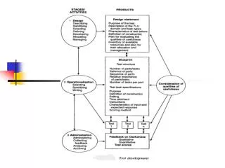
DESIGN PROCEDURE ASCE 7-05 ACI 318-02 CRSI 2002 Design Manual E-TABS Unit Strip Method PCA Slab And Column Hand Calculations
STRUCTURAL OVERVIEW 6” Normal Weight Concrete Slab-CIP 16” x 28” CIP Beams 20” x 26” CIP Girders 20” x 30” CIP Columns Moment Frames Design Floor And Roof Loads:
SLAB DESIGN • 4000 PSI Concrete, 60 KSI Steel Reinforcing • Minimum 5” Thick Concrete Slab Based On ACI • 6” Thick Concrete Slab Was Used • Pattern Loading Considered To Find Critical Moments • Steel Reinforcing • Bottom: #3’s @ 8” O/C (Positive) • Top: #4’s @ 12” O/C (Negative) • T-S: #4’s @ 15” O/C
COLUMN DESIGN Designed For 1300 Kips and 750 K-FT Gravity and Lateral Loads Slenderness Considered Based On ACI For Lateral Loads 4000 PSI Concrete # 3 Ties
COLUMN DESIGN 20” x 30” CIP Column 32 #10 Bars Oriented So That The 30” Depth Handles The Larger Wind Force In The Long Direction
BEAM DESIGN • Moment and Shear Coefficient Analysis • 16” x 28” Beam • Steel Reinforcing • Bottom: 2 #11’s • Top: 2 #11’s • Stirrups: #5’s • L/370 Deflection Ratio
GIRDER DESIGN • Moment and Shear Coefficient Analysis • 20” x 26” Girder • Steel Reinforcing • Bottom Bars: 3 #11’s • Top Bars: 4 #14’s • #5 Stirrups • L/706 Deflection Ratio
MOMENT FRAMES • Designed To Resist Lateral Loads In Both Directions • Achieved From CIP Monolithic Pour At Every Connection • For Simplicity Of Lateral System And Ease Of Construction, Every Column And Beam Connection Is A Moment Connection • Forces Distributed By Relative Stiffness • 32 Moment Frames • 6 In The Short Direction • 26 In The Long Direction
LATERAL DRIFT • Combination Of Shear Deflection And Bending Deflection • Controlled By Wind • Drift Found To Be Less Than 1” In Both Directions • 0.2” In Long Direction • 0.15” In Short Direction
ADVANTAGES OVER EXISTING STRUCTURAL SYSTEM Floor Depth Savings: 5” Beam Deflection Savings: 0.7” Girder Deflection Savings: 0.4” # Of Column Savings: 76 Drift Savings: 0.37”
EXISTING STRUCTURAL SYSTEM • Cost Estimate #1: $8.62 Million • Estimate Based On G.C.’s Suggestions And Feedback • Cost Estimate #2: $7.71 Million • Estimate Based On R.S. Means 2008 • Detailed Estimate Based On Takeoff Per L.F. Of Steel • Cost Estimate #3: $8.67 Million • Estimate Based On R.S. Means 2008 • Generic Steel Estimate Based On A 3-6 Story Steel Building
EXISTING STRUCTURAL SYSTEM Schedule For Estimate #1: N/A Schedule For Estimate #2: 5 Months Schedule For Estimate #3: 5 Months
PROPOSED STRUCTURAL SYSTEM • Cost Estimate #1: $13.46 Million • Based On R.S. Means 2008 • Detailed Estimate Based On Takeoff • Cost Estimate #2: $12.44 Million • Based On R.S. Means 2008 • Generic Estimate Based On CIP One-Way Slab W/Beams and Columns
PROPOSED STRUCTURAL SYSTEM Schedule For Estimate #1: 15 Months Schedule For Estimate #2: 15 Months
PROBLEM STATEMENT • There Is An Excessive Amount Of Transformers • Currently There Are 50 Transformers • GOALS: • Reduce Number Of Transformers • Resize The Feeders
SOLUTION EXAMPLE BEFORE: AFTER:
SOLUTION EXAMPLE • LEFT SIDE: • Transformer Savings: 5 • Connected Load: 53 KVA-Telecommunications • Replaced With 75 KVA Eaton 480V-208/120V • Replaced Feeder With 2 Sets Of 4 KcMilWire
SOLUTION EXAMPLE • RIGHT SIDE: • Transformer Savings: 3 • Connected Load: 35 KVA-Telecommunications • Replaced With 45 KVA Eaton 480V-208/120V • Replaced Feeder With 2 Sets Of 4 KcMil Wire
REDESIGN OVERVIEW Transformers Before: 50 Transformers After: 11 Savings: 39 Utilized Eaton 480V-208/120V Transformers
RECOMMENDATION • Keep Structural System As Steel Composite System With Braced Frames For The Following Reasons: • Cost • Erection Time
CONCLUSIONS Initial Cost Analysis Was Proven Wrong Recommend Keeping Existing Structural System Able To Reduce The Number Of Electrical Transformers
ACKNOWLEDGEMENTS KlingStubbins, Especially Bill Gillespie Dr. Hanagan, Professor Parfitt And The Rest Of The AE Department Ben Kovach At Balfour Beatty Pennsylvania State University Fellow AE’s My Family And Friends