Download
1 / 21
210 likes | 380 Views
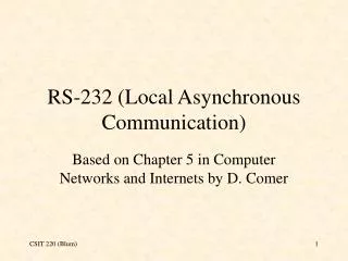
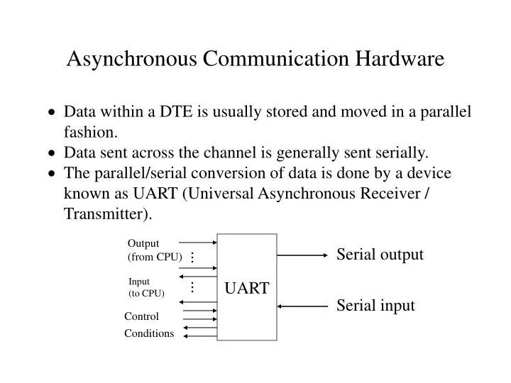
Asynchronous Communication Hardware. Data within a DTE is usually stored and moved in a parallel fashion. Data sent across the channel is generally sent serially. The parallel/serial conversion of data is done by a device known as UART (Universal Asynchronous Receiver / Transmitter). Output

E N D
Asynchronous Communication Hardware • Data within a DTE is usually stored and moved in a parallel fashion. • Data sent across the channel is generally sent serially. • The parallel/serial conversion of data is done by a device known as UART (Universal Asynchronous Receiver / Transmitter). Output (from CPU) UART Serial output ... Input (to CPU) ... Serial input Control Conditions
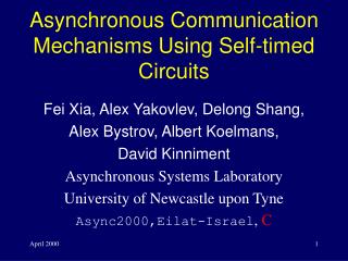
Start Byte (from processor) To channel Shift clock Channel From shift register XOR Initial value UART Transmission • Convert internal parallel byte into a stream of serial bits. Parity generation
UART Transmission • Single shift register: Once the UART has sent a byte, the processor can be signaled that the UART is ready to transmit another byte. Time Processor UART Channel 1 supplies byte to UART Idle 2 shifts data bits Active 3 shifts data bits Active . . shifts data bits Active . 9 signals completion to processor Idle 10 supplies byte to UART Idle 11 shifts data bits Active 12 shifts data bits Active
Holding register To channel Double Buffering • A second register, a Transmit holding register, is placed between the processor and the UART. Byte (from processor) Shift register Time Processor Hold Reg. Shift Reg. Channel 1 supplies byte to HR empty empty Idle 2 supplies bytes to SR empty Idle 3 signals processor shifts data bits Active 4 supplies byte to HR empty shifts data bits Active 5 data shifts data bits Active 6 supplies bytes to SR shifts data bits Active 7 signals processor shifts data bi Active
UART Reception • UART is in an idle receive state while the channel is in an idle (mark) state. • Upon detection of a channel state change (Mark to Space), UART determines the center of the start bit and then reads bits from the channel at regular intervals using a sampling clock. • The bits are assembled in a shift register. • Bits in the register are shifted to the right at each clock tick. • When all bits have been read from the channel, the resulting byte is supplied to the processor. Sampling clock Shift register channel Holding register Byte (to processor)
UART Reception • The algorithm to find the center of the start bit: • Underlying assumption: transmitter and receiver agree to a common bit rate. 1. Wait for a mark-to-space transition. 2. When a transition has been found, sample the line at 16 times the bit rate. 3.After 8 ticks (1/2 bit time), sample the line: - if space (0) is found, a start bit is assumed and the line can be sampled once per bit time. - if a mark (1) is found, a false start bit was found, and the line sampling can be abandoned.
PC UART • A typical PC is supplied with at least an UART (serial port). • Most PC UARTs are compatible with Intel 8250 UART. • The 8250 UART is programmable and permits: • UART can signal the processor with the following status: - A variable word size (5-, 6-, 7-, or 8-bit words). - A variable number of stop bits (1, 1.5, 2). - A choice of parity (none, mark, space, odd, or even). - A choice of line speeds (50 to 9600 bps or higher). - Data ready (in receive buffer). - Reception errors (overrun, parity, framing). - Break condition (in the Space state for one complete frame) detected. - Transmit shift register empty. - Transmit holding register empty.
Programming the UART • The line speed, word size, parity, and the number of stop bits must be written to the UART before it can be used. • The UART’s line speed is generated by dividing its internal clock rate (1.8432 MHz) by a programmable 16-bit divisor (saved in the two line speed registers). • The value resulting from the division is 16 times the actual line speed. Divisor (Hex) Line Speed 0x0900 50 0x1800 300 0x0060 1200 0x0030 2400 0x000C 9600
UART Port Addresses and Functions Port 1 Port 2 Address Offset Uses 0x3F8 0x2F8 Base address + 0 Transmission Register Buffer Receive Register Buffer Line Speed (LSB) 0x3F9 0x2F9 Base address + 1 Interrupt Enable Line Speed (MSB) 0x3FA 0x2FA Base address + 2 Interrupt Identification Register 0x3FB 0x2FB Base address + 3 Line Control Register 0x3FD 0x2FD Base address + 5 Line Status Register
7 6 5 4 3 2 1 0 Word length Number of stop bits Parity enable Even parity select Stick parity Set break Divisor latch access Line Control Register • If bit 7 of LCR is set, ports 0x3F8 and 0x3F9 can be accessed as the line speed divisor registers. • The word size, parity, and stop bits are also initialized through LCR.
7 6 5 4 3 2 1 0 Word length Number of stop bits Parity enable Even parity select Stick parity Set break Divisor latch access Line Control Register bit 1 bit 0 word Length 0 0 5 0 1 6 1 0 7 1 1 8 bit 2 word Length #stop bits 0 any length 1 1 5 1.5 1 6,7,8 2 Parity bit 5 bit 4 bit 3 Even odd mark space 0 1 1 0 0 1 1 0 1 1 1 1
7 6 5 4 3 2 1 0 1 1 0 1 0 Word length Number of stop bits Parity enable Even parity select LCR Example #define DLABon 0x80 #define DLABoff 0x00 #define BPS96k 0x0c #define SEVENBIT 0x02 #define STOPBITS 0x00 #define PRTYENA 0x08 #define EPS 0x10 #define DIVLTCHLSB 0x3F8 #define DIVLTCHMSB 0x3F9 #define LCR 0x3FB initialize() { outportb(LCR, DLABon); outport(DIVLTCHLSB, BPS96K); outportb(LCR, DLABoff+SEVENBITS+STOPBITS+PRTYENA+EPS); }
UART Transmission - 0x3F8 transmission holding register Main( ) { char ch; /* initialize UART */ for (ch = ‘A’; ch <= ’Z’ ; ch++) outportb(0x3F8, ch); } - not all of the bytes will be sent because the processor is faster than UART.
7 6 5 4 3 2 1 0 Data Ready Overrun error Parity error Framing error Break detected Transmit holding register empty Transmit shift register empty 0 Line Status Register
UART Transmission by Polling #define TXR 0x3F8 #define LSR 0x3FD #define THRE 0x20 main( ) { char ch; /* initialize UART */ for (ch = ‘A’; ch <= ’Z’ ; ch++) { while ((inportb(LSR) & THRE) == 0) ; outportb(TXR, ch); } }
UART Reception by Polling #define RCVR 0x3F8 #define LSR 0x3FD #define DA 0x01 main( ) { /* initialize UART */ for ( ; ; ) { while ((inportb(LSR) & DA) == 0) ; printf(“%c \n”, inportb(RCVR)); } }
7 6 5 4 3 2 1 0 UART Interrupts - Polling wastes processing power. - UART generates 4 types of interrupts (interrupt enable register). - UART IER initialization: #define IER 0x3F9 #define DATA_AV 0x01 #define TX_HR_MT 0x02 #define RVC_LS 0x04 #define MDM_CHG 0x08 uart_init( ) { /* other initialization statements */ outportb(IER, DATA_AV+RCV_LS), } Data available Tx holding reg. empty Receive Line Status Modem status change
UART Interrupts - 8259 initialization: 8259 interrupt control mask register 7 6 5 4 3 2 1 0 #define INT_MASK 0x21 #define CLKENA 0xFE #define KEYENA 0xFD #define SP1ENA 0xEF #define SP2ENA 0xF7 #define PPENA 0x7F void initialize( ) { /* other initialization statements */ outportb(INT_MASK, CLKENA & KEYENA & SP1ENA &SP2ENA, PPENA); } UART 2 UART 1
UART Interrupts - Interrupt identification register indicates the cause of the interrupt. Interrupt identification register 7 6 5 4 3 2 1 0 IIR Interrupt 6 Receive line status (overrun, parity error, etc.) 4 Received data available 2 TX holding Reg. empty 0 Modem status change Interrupt pending Interrupt id (b0) Interrupt id (b1)
Example: PC telephone utility - whatever is typed on one terminal also appear on the other terminal. - Each screen is divided in half, with upper half showing local input and lower half showing remote input. - Two PCs are connected via their serial ports. - When a character is entered, it should be displayed on the local half screen and also transmitted. Characters received from serial port are displayed at remote half screen. - End-of-session is indicated by Crtl-C. - Once a half screen is filled, it is cleared.
Implementation do_pt2pt( ) KEYIH do_lcl_scr() XMITDONE SPxIH do_rmt_scr()