Download
1 / 53
570 likes | 746 Views
Two-Way Time Transfer (TWTT). Jeremy Warriner, Symmetricom. Time Interval Counter. CH2. CH1. TWTT Overview. Local Clock. Phase offset between two clocks can be determined using Two-Way Time Transfer (TWTT) technique A pulse is transmitted by each clock at the top of the second

E N D
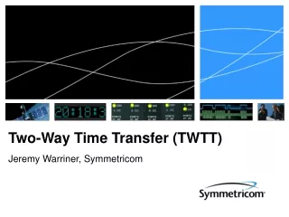
Two-Way Time Transfer (TWTT) Jeremy Warriner, Symmetricom
Time Interval Counter CH2 CH1 TWTT Overview Local Clock • Phase offset between two clocks can be determined using Two-Way Time Transfer (TWTT) technique • A pulse is transmitted by each clock at the top of the second • Time difference transmitting a pulse and receiving a pulse from the remote clock is measured • The difference of the two measurements is twice the clock offset • Requires that the path delay be symmetric and requires a mechanism for sharing the measurements between the two sites A dAB dAB = dBA Time Interval Counter CH1 CH2 dBA B Remote Clock MEASLOCAL = A – (B + dBA) MEASREMOTE = B – (A + dAB) (MEASREMOTE - MEASLOCAL) / 2 = B – A = Remote Clock Delay
Time Transfer Modem • Time Transfer Modem (TSC 4402) technology development completed using program funding • Time Transfer Modem accepts clock inputs and generates a coherent waveform at an IF that can then be transmitted over RF links • Time difference measurements are made between the transmitted waveform and the received waveform • Measurements are shared between the two sites using the established RF link • Modem calculates the relative clock offset between the two sites and provides the information to the user T1 T2
ATS 6502 • Original modem has been replaced with the ATS 6502 • Technology and specialized hardware remains unchanged but the power and timing distribution is improved • Integrated power control allows hardware to be powered on sequentially to eliminate race conditions • Front panel interface added to ease setup • Calibration data stored on the hardware so software can be updated with no impact to the calibration • Improved thermal management allows for more air flow and cooler operating temperatures • Capability to integrate Rb oscillator internal to the system and provide local time recovery • Capability to integrate GPS receiver internal to the system and provide positioning information as well as backup to TWTT timing • Form factor is extended to full rack width of a 2U instrument instead of the half rack TSC 4402 version TSC 4402 - Time Transfer Modem ATS 6502 - Time Transfer Modem
PCI BUS Rx Filter / AGC Tx Filter Block Diagram 10 MHz 1 PPS NTP ATS 6502 Single-board Computer NTP Time-based Transmitter 10 MHz IN RF Motherboard 1 PPS IN IF OUT IF OUT IF IN 10 MHz IN 10 MHz OUT 50 MHz OUT Digital Processor Two-Channel Digitizer Tx IF Sample CLK IF IN CH 1 (Tx) HSI HSI Rx IF CH 2 (Rx)
Block Diagram Explained • Clock inputs are accepted by the ATS 6502 and used to generate an IF waveform within the time based transmitter • Transmitted and received IF waveforms are digitally sampled by the two-channel digitizer • Sampled waveform data is passed to the digital processor over a high speed interface (HSI) • Digital processor calculates the time difference between the transmitted signal and received signal • Measurement passed to the computer using the PCI bus • Measurement information is passed to the time-based transmitter via the PCI bus and transmitted to the remote site via the RF link • Once the local and remote measurement is received by the computer it calculates the relative clock offset between the two sites
IF Waveform • Waveform generated by the Time Transfer Modem must fulfill two requirements • Must be coherent with the reference clock being measured • If the waveform is not coherent with the reference clock then the clock offset provided by the system will be that of the internal oscillator and not the reference • Must include a unique event in time that can be measured • Without a unique event the system has no way of ensuring that the event being measured locally is the same event that was measured by the remote site • Synchronous data link structure developed to provide timing markers at regular intervals • Timing markers are unique and provide an event in time that the system can measure • Unused data bandwidth is available to users for data transfer • Also used for transferring the timing measurement to the remote system
Signal Structure 1000 0 250 500 750 Time (ms) Frame Structure – 16 bits (12 bits fixed (1’s), 4 bit counter) Data Structure, Size = 2368 data bits / second on a 2.5 kbit/sec link = 276 bytes / second GPS Second Counter, 32 bits Station Identifier, 32 bits Fixed bit (0) Totals: 625 bits / frame, 4 frames / second, 276 bytes / second
Measurement Event • The time difference between transmitting the first data bit of the framing pattern and receiving the first data bit of the framing pattern from the remote modem is the desired measurement event • Measurement process is repeated for all 2500 bits within the second • Measurements are then averaged to improve the system performance MEASLOCAL TX 1000 RX 1000 0 250 500 750 Local Time (ms)
Clock Measurement ATS 6502 Measurement Precision • Clock offset is obtained by differencing the measurements from the two modems and dividing by two • Process is completed automatically by the ATS 6502 modem • Clock offset data collected from two time transfer modems co-located in a laboratory • Both modems running off of the same input reference σ = 2.36 ps ATS 6502 (Local) Tx IF Clock Offset (2 ps / div) Rx IF ATS 6502 (Remote) Tx IF Rx IF Time (0.2 Hours / div) 1000
Static TWTT • Static two-way time transfer involves making simultaneous time difference measurements between two fixed points on the earth • In the static case, propagation delay to the satellite cancels and two-way equation reduces to: delay1 delay2 delay4 delay3 MEASLocal= T1 – (T2 + delay3 + delay4 + Sagnac12) MEASRemote= T2 – (T1 + delay2 + delay1 + Sagnac21) T1 T2 delay1 + delay2 = delay3 + delay4 Where SAGNAC is a time-of-flight measurement effect and is a constant In Static Two-Way Time Transfer, all of the data corrections are constants and can be computed ahead of time
Dynamic TWTT • Dynamic TWTT is identical to static TWTT except that one or both of the platforms may be moving during the measurement interval • Propagation delay of signals no longer cancels • Sagnac effect is time varying instead of being a constant • TWTT equation must be modified to use corrected TWTT measurements instead of raw TWTT measurements delay1 + delay2 ≠ delay3 + delay4 delay2 delay1 delay3 delay4 2
Corrected TWTT Measurements • Corrected TWTT measurements are comprised of the raw measurement and two correction terms • First term corrects for platform motion during the measurement interval • Second term corrects for changes in path delay due to Sagnac effect • Raw measurement can be corrected before transmitting the measurement to the opposite side of the link • Reduces the amount of data that needs to be transmitted Where, 2
Correction for Platform Motion • Correction for platform motion given by the above equation • First term corrects the TWTT measurement for the motion of the platform when both timing signals are transmitted simultaneously • Second term corrects the TWTT measurement for non-coincident times of transmission • Speed of light terms in the denominator reduces the effect of position errors on the TWTT algorithm • Remote platform refers to the satellite in the case of a satellite relay xloc = position vector (ECEF datum) of the local platform xrem = position vector (ECEF datum) of the remote platform vloc = average velocity vector (ECEF datum) of the local platform during the measurement interval tloc = time the local timing signal is transmitted trem = time the remote timing signal is transmitted c = speed of light.
Correction for Sagnac Effect • Correction for the Sagnac effect on the TWTT measurement given by above equation • Sagnac does not change appreciably over the measurement interval but the effect is seen when larger distances have been traveled by one of the platforms • The speed of light term in the denominator reduces the effect of position errors on the correction • Remote platform refers to the satellite in the case of a satellite relay w = angular velocity of the Earth xloc=position vector (ECEF datum) of the local platform xrem= position vector (ECEF datum) of the remote platform c = speed of light.
Test Plan • Characterize the offset between two Cesium clocks (HP 5071A) prior to the flight test • Clocks are co-located at Kirtland AFB • Time offset measured using a time interval counter (TIC) • Transport the flight clock to the aircraft • Clock remained operational on battery power • Measure the offset between the flight clock and the ground clock using TWTT • Two independent TWTT systems operated throughout the flight • Both systems measure the time offset between the flight clock and the ground clock • Measurement between the two systems should agree because they both measure the same physical quantity • Using different satellites for the communication link creates significantly different dynamics for the system • Difference appears in the raw TWTT measurements (presented later) • Real-time TWTT corrections must be correct or the clock offset calculated by the two systems will not agree • Transport the flight clock from the aircraft to the hangar • Clock remained operational on battery power • Characterize the offset between the ground clock and the aircraft clock using a TIC
Flight Test Intelsat 707 (53º West) Intelsat Americas 7 (129º West) Side B Side A Big Crow, C-135 Kirtland AFB, NM
Ground Setup • Ground clock was a Cesium reference (HP 5071A) and provided timing signals (10 MHz, 1 PPS) to both TWTT systems • Each ground terminal comprised of a 0.75 meter dish and 25 Watt Transceiver • TSC 4400 (GPS Time & Frequency Reference) used to provide NTP to the TSC 4402 (Time Transfer Modem) GPS Antenna Side A Side B HP 5071A
Aircraft Setup Timing Rack RF Rack • Flight clock was a Cesium reference (HP 5071A) and provided timing signals (10 MHz, 1 PPS) to both TWTT systems • RF equipment and timing equipment separated into two co-located racks on the aircraft • Two independent Ku-band antennas (24 inch) installed under radome • Each antenna tracks a geostationary satellite in azimuth, elevation, and polarization Side B Side A
Flight Path • Take Off: 0740 MST, Wednesday April 5th, 2006 • Landing: 1350 MST, Wednesday April 5th, 2006
TWTT Data (Raw) Raw TWTT Measurements • Traditional TWTT calculation performed on flight data • No corrections made for platform motion or Sagnac effect • Dominant effect seen in raw data is a result of aircraft motion during the measurement interval • Only motion in the direction of signal propagation causes error • 140 ns of variation seen during this test • Raw TWTT measurements are considerably different because two different satellites are used Offset (20 ns/division) Time (1.2 hours/division)
TWTT Data (Corrected for Motion) • Data corrected for platform motion • Discrete jumps in measurement no longer present • No corrections have been made for the Sagnac effect TWTT Measurements (Motion Corrected) Offset (10 ns/division) Time (1.2 hours/division)
TWTT Data (All Corrections Applied) • TWTT data corrected by the terms for platform motion and the Sagnac effect • Measurements from both TWTT systems agree • Validates the real-time corrections Real-time TWTT Data (60s Avg) Offset (2 ns/division) Time (1.2 hours/division)
TWTT Accuracy (60s Avg) • Real-time TWTT data is consistent with the “truth” data from before and after the flight • TWTT data provides a record of what happened to the clock during the flight • Measurements from two independent TWTT systems are consistent with each other • Mean offset between systems was 0 ns • RMS difference between systems was 860 ps over the duration of the flight Real-time TWTT Data (60s Avg) Difference Between Measurements RMS = 860 ps Offset (2 ns/division) Offset (2 ns/division) Time (1.2 hours/division) Time (1.2 hours/division)
Real-time TWTT Data • Real-time data collected on 1 second measurement intervals • Side A system had difficulty maintaining lock during the first half of the flight • Appeared to be related to the look angle through the radome • Side B system noisy due to two satellites being close enough in orbit that the timing signal passed through both satellites creating a multi-path scenario Real-time Measurements – Side B Real-time Measurements – Side A Offset (5 ns/division) Offset (5 ns/division) Time (1.2 hours/division) Time (1.2 hours/division)
Real-time Performance • Residual between two systems used to estimate real-time performance • 1 second measurements from side A compared to the 60 second average of side B (served as truth) • Exploded view of “good” section shows the expected performance of the system • This is what the system performance would have looked like if there weren’t issues with the RF link during the first part of the flight Real-time Performance Expected Performance σ = 600 ps σ = 1.34 ns Residual (2 ns/division) Residual (2 ns/division) Time (15 minutes/division) Time (1.2 hours/division)
Static Testing • Objective • Characterize performance of dynamic TWTT system (TSC 4402) operating over a static baseline • Description • Compare TWTT measurements of the same event using two independent systems • Event: Clock offset between U.S. Naval Observatory and Symmetricom (Boulder) • System 1: TSC 4402 (Device under test) • System 2: Timetech SATRE TWSTFT Modem (Baseline) • Differences in the measurements represent the combined measurement error of the two systems • Experimental setup (diagram on next slide) • Each site clock used as a common reference for both TWTT systems • Both TWTT systems utilize same type of Ku-band transceiver • Minimize performance differences due to ancillary equipment • Each TWTT system operated over a different satellite • Effects from satellite motion will be different for the two systems
Experimental Setup AMC-1 (129º West) Intelsat 707 (53º West) Size: 1.8 meter BW: 3.0 MHz Data Rate: 0.25 kbps Code: 6 Size: 1.8 meter BW: 3.0 MHz Data Rate: 0.25 kbps Code: 7 Size: 1 meter BW: 2.5 MHz Data Rate: 10 kbps Code: 11 Size: 1 meter BW: 2.5 MHz Data Rate: 10 kbps Code: 27 Symmetricom (Boulder) U.S. Naval Observatory
Antenna Configuration • SATRE TWTT system • 1.8 meter dish • 4 Watt Ku-band Transceiver • Anasat 4Ku • Symmetricom TWTT system • 1.0 meter dish • 4 Watt Ku-band Transceiver • Anasat 4Ku 1.8 meter 1.0 meter Symmetricom (Boulder)
Performance Comparison • Comparison of the data between the systems is as expected • Short-term noise is comparable • Long-term agreement is very good • Medium-term variations dominate the measurement noise • Result mostly from using short code lengths (127 bits) on TSC 4402 (discussed later) • Only significant disagreement occurred during a snow storm in Boulder • System returned to normal when the sun came out and began melting the snow TWTT Data (60 sec average) Difference (60 sec average) σ = 1.25 ns Offset (2 ns / division) Residual (1 ns / division) Snow Storm Time (0.5 days / division) Time (0.5 days / division)
Medium Term Variations • Medium term variations are the result of an effect referred to as code-contamination • The TSC 4402 uses Gold codes as the chipping code for generating a direct-sequence spread spectrum signal • Gold codes are families of codes that exhibit well behaved cross-correlation properties • Gold codes from the same family look like pseudo-random noise to each other when they are summed together • The longer the Gold code sequence the lower the “noise” floor appears to other codes in the family • TSC 4402 uses 127 bit Gold codes whereas systems such as GPS use 1023 bits • Noise from other codes is not truly random and can affect the timing measurement differently depending on how the codes are summed together
1 1 1 0 0 0 1 1 0 1 1 1 1 0 0 0 0 0 Effect of Satellite Motion • Satellite motion causes changes in path delay from the ground stations to the satellite • Changes in path delay cause the timing signals from the ground station to sum together differently over time (represented by the changing colors in the summed signal) Symmetricom (Boulder) U.S. Naval Observatory Code 1 Code 2 Sum
Evidence of Code Contamination TWTT Data (TSC 4402) • If code contamination is a significant portion of the medium term noise than the variations should repeat on a diurnal cycle • Plots show data from the same time on two different days • Strong correlation between the major noise components of both plots • Supports claim that major noise component of the system is from code contamination Offset (1 ns / division) Time (1.2 hours / division) TWTT Data (TSC 4402) Offset (1 ns / division) Time (1.2 hours / division)
Static vs Dynamic • Why does the TSC 4402 perform better in dynamic applications than it does in static ones? • In dynamic applications the path delay to the satellite changes much quicker and thus the measurement variations occur on a much shorter timescale • Significant portions of the variation are averaged out by the 1-second measurement interval Static Test Result (1 sec) Flight Test Result (1 sec) Expected Performance σ = 0.6 ns σ = 1.3 ns Residual (1 ns / division) Residual (1 ns / division) Time (15 min / division) Time (0.5 days / division)
Improving Static TWTT Performance • Increasing Gold code length • Increasing the code length provides better cross-correlation properties with other codes and reduces the amount of “contamination” between codes • Increasing the code length in the TSC 4402 requires that the data rate be reduced in order to occupy the same signal bandwidth • Data rate will be reduced from 10 kbps to 2.5 kbps when the code is extended from 127 bits to 511 bits • Work performed under current contract • Changing the point of coincidence for the system • Currently the system transmits the timing signals so that they leave the Earth stations at the same time • Transmission time can be adjusted so that the timing signals arrive at the satellite at the same time • Ensures that signals always sum with the same phase relationship and thereby removes the time varying component of code contamination • Loopback signal from the satellite serves to range the satellite and continually adjust the time of transmission • Adjustments to the time of transmission must be corrected in the TWTT measurement data • To be investigated under new contract (discussed later)
Extended Gold Code • Gold code length extended from 127 bits to 511 bits to improve timing performance in static scenarios • Characterization of performance improvement completed using identical test setup as before between Symmetricom and USNO • Standard deviation improved from 1.3 ns to 0.95 ns ATS 6502 (black) vs SATRE (red) TWTT Comparison σ = 0.952 ns Residual (1 ns / division) Offset (1 ns / division) Time (1.2 hours / division) Time (0.5 day / division)
Improving performance • FY08 funding • Characterize the fundamental limits of the current TWTT technology • Identify potential improvements to the TWTT technology that will enable precise TWTT (sub-100ps) • Prototype the precise TWTT system and characterize the performance improvement • Primary areas of interest • Error contributions of dynamic TWTT corrections • Alternative signal structures that may yield improved measurement performance • Systemic errors induced by hardware and temperature variations • System architecture changes that can improve TWTT performance
TWTT Error Budget • Current TWTT error budget identifies multiple areas requiring enhancements in order to break the 100 ps barrier • Error contribution for static scenarios and dynamic scenarios may be different but the budget incorporates the error from the worse of the two scenarios • Primary error sources • Architecture: Variations due to the overall system architecture design • RF link: Variations introduced by the details of the RF link budget • Hardware: Variations introduced by systemic hardware issues such as temperature coefficients • Corrections: Variations introduced by uncertainty in the correction terms applied to TWTT measurements • Atmosphere: Variations introduced by non-symmetric delays through the atmosphere SOURCE ERROR
System Architecture Geostationary Satellite • System architecture for TWTT design focused on maximizing scalability of the system and portability of TWTT terminals while achieving sub-ns real-time performance • TWTT terminals were to be easily added to a network as well as be able to operate from small ground stations and airborne platforms • Code Division Multiple Access (CDMA) technique chosen to allow multiple terminals to operate simultaneously in the same frequency band Master Channel Measurement Channel 1 Measurement Channel 2 Distress Channel Slave N Master 1 Master 2 Master Standby 2 Slave 1 Slave 2 Slave N-1 Master Standby 1 LAN LAN
System Architecture (cont.) • CDMA architecture implemented using Gold codes to generate a direct sequence spread spectrum BPSK signal • Low data rate signal (2.5 kbps) is spread across a wider frequency bandwidth (2.5 MHz) by chipping the data signal with a Gold code • Use of Gold codes allows all stations to transmit at the same frequency • Stations are distinguished by their code • Spread spectrum communication signal provides a wide bandwidth signal with a relatively low data rate • Wider bandwidth signals improve the measurement precision of the system • Lower data rate (2.5 kbps) enables the use of small 1-meter antennas 2.5 MHz Signal Current TWTT Ground Terminal
Architecture Limitations • Transmitting all signals on the same frequency channel introduces error due to non-zero cross-correlation values between the signals • Increasing the Gold code length improves the cross-correlation properties but reduces the overall data rate that can be transmitted in the same frequency bandwidth • Error introduced by this effect is on the order of 650 ps for the 511 bit Gold code operating at a 2.5 kbps data rate • Two options for reducing error contribution of the system architecture • Move the point of coincidence for the system from the ground terminals to the satellite • Change architecture to use frequency division of signals so that they no longer occupy the same spectrum and interfere with one another
1 1 1 0 0 0 1 1 0 1 1 1 1 0 0 0 0 0 Architecture Enhancement • Changing the point of coincidence involves measuring the range to the satellite and adjusting the time at which the signal is transmitted so that it always arrives at the satellite at the top of the second • Causes the Gold codes from the various ground terminals to always sum in the same way and removes the time-varying portion of the error • Error bias still exists but it no longer varies in time so it can be calibrated Symmetricom (Boulder) U.S. Naval Observatory Code 1 Code 2 Sum
Architecture Change • Changing system from a code division architecture to a frequency division architecture reduces interference between signals from different TWTT terminals • Eliminates errors due to non-zero cross-correlation properties • Easier to support larger data rates because it is no longer necessary to maintain cross-correlation properties by utilizing higher order Gold codes • Easier to support asymmetric data rates on the forward and reverse data links because there are no cross-correlation properties to maintain • As with any trade-space, compromises must be made in other areas to achieve the increased performance • Requires more EIRP for same performance because bandwidth and SNR are not equivalent contributors to Cramer-Rao inequality • Introduces additional asymmetry in group delay between the TWTT terminals because they no longer occupy the same frequency space and therefore go through different parts of the satellite transponder • Placing signals close to each other in frequency helps mitigate this effect
Architecture Change (cont.) • Primary benefit of architecture change is that it allows the investigation of alternative signal structures that may improve measurement performance • Offset Frequency Division Multiplexing (OFDM) allows the use of carrier phase measurement techniques in addition to the code phase measurements currently being made • OFDM signal is comprised of multiple sub-carriers which each contain their own modulated data stream • Code phase of the individual carriers is used in making a coarse timing measurement • Precise timing measurement is performed by measuring the differential phase of the individual sub-carriers within the OFDM signal • Allows the use of low-noise phase measurement technologies developed under other projects vd = dΦ / df OFDM Signal
RF Link • RF link budget affects performance according to the Cramer-Rao inequality and is bounded by the signal bandwidth, SNR, and integration period • Portable ground terminals used in current TWTT architecture limit system performance to around 550 ps • Performance threshold can be improved by increasing the dish size or transmitted power • Changing the system architecture from a CDMA scheme to a frequency division scheme decreases measurement accuracy versus EIRP ratio • Signal bandwidth has larger effect of measurement performance than does SNR • System performance can be enhanced as necessary by increasing the transmitted data rate and EIRP Current TWTT Ground Terminal
Hardware Constraints • Measurement errors introduced by hardware at the TWTT ground terminals is around 400 ps • Primary measurement error is due to temperature variations within the modem and Ku-band transceiver • Decreasing error contribution of hardware can be accomplished by either decreasing the temperature coefficient of the system or calibrating out temperature effects • Both methods are to be investigated • L-band BUC is to be analyzed for delay variation with respect to temperature • Currently use a 70 MHz IF input to the transceiver but L-band BUC does not include as much signal filtering and may have a better temperature coefficient • Requires incorporating a L-band IF signal as part of the time transfer modem • Calibration of time transfer modem is to be performed with respect to temperature • Allows the removal of a significant portion of the delay variation within the modem Modem Delay Variations Due to Temperature σ = 175 ps Delay (100 ps/division) Time (2 Hours/Division)