Microcontroller Programming II MP6- 1
560 likes | 820 Views
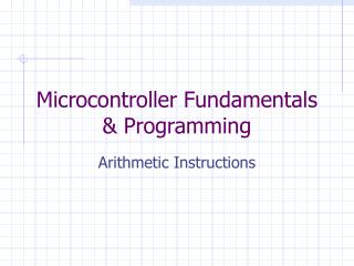
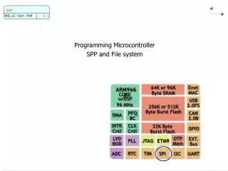
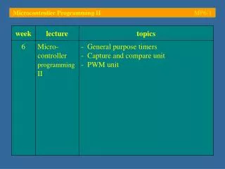
Microcontroller Programming II MP6- 1. Microcontroller Programming II MP6- 2. General Purpose Timers. - One of the most important issues in embedded control is the programming of timers.

Microcontroller Programming II MP6- 1
E N D
Presentation Transcript
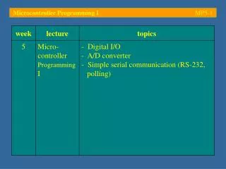
Microcontroller Programming II MP6-2 General Purpose Timers - One of the most important issues in embedded control is the programming of timers - Without accurate timing, digital control engineering is not possible – the control signals (controller action) have to happen at the exact right moment in time, e.g. timing control of an engine, etc. - Large embedded systems are often centred around small real-time kernels which offer services for multi-tasking applications; smaller applications make use of Interrupt Service Routines (ISR) to achieve accurate timing control
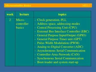
Microcontroller Programming II MP6-3 General Purpose Timers - The General Purpose Timer unit of the C167CR (GPT1 – there are 2 such units) is controlled through a number of Special Function Registers (SFR)
Microcontroller Programming II MP6-4 General Purpose Timers - GPT1 consists of three 16-bit timers (T2, T3, T4) Each of these timers can be configured as…… timer,… gated timer,… counterand… incremental interface mode
Microcontroller Programming II MP6-5 General Purpose Timers - In timer mode, the timer register is incremented with every tick of the internal clock source - In gated timer mode, the (internally incremented) timer can be switched on/off via an external signal - In counter mode, the counter register is incremented with rising/falling/both edges of an external signal - The incremental interface modesupports interfacing to incremental encoders; both rate and direction are determined and the counter register is incremented / decremented accordingly
0xFFFF Initial value 0x0000 duration 0 Tinit Tmax Microcontroller Programming II MP6-6 General Purpose Timers - Timers are probably best explained using the following diagram: - The timer register is loaded with an initial value; it is decremented at a fixed rate – the timer elapses when the timer register reaches 0
Microcontroller Programming II MP6-7 General Purpose Timers - Core timer T3 is configured for timer mode through its control register T3CON - Setting T3M (mode) to binary 000 puts T3 into timer mode; field T3I then controls the frequency with which the timer register is updated; T3UD specifies the direction of this update (up/down); T3UDE enables the external control of this direction
Microcontroller Programming II MP6-8 General Purpose Timers - The timer clock frequency is generated by pre-scaling the CPU clock (fCPU):
Microcontroller Programming II MP6-9 General Purpose Timers - The timer is switched on or off using bit T3R in Special Function Register T3CON - T3OE allows the state of the output toggle latch (T3OTL) to be displayed on pin T3OUT (= P3.3); T3OTL changes its state whenever the timer elapses
Microcontroller Programming II MP6-10 General Purpose Timers - An elapsed timer usually triggers an interrupt; on the C167, every timer comes with its own Interrupt Control register (TxIC) - The T3IC register allows a priority value to be specified (group level, interrupt level); in the case of several simultaneous interrupts, this value is used to determine which interrupt should be serviced first
Microcontroller Programming II MP6-11 General Purpose Timers - Example:Toggle the LED connected to port P3.3 at a fixed rate of 0.25 seconds (ON : 250 ms, OFF : 250 ms) 5V PORT3
65535 39009 0 0 s 250 ms 420 ms Microcontroller Programming II MP6-12 General Purpose Timers - The table on slide MP6-8 indicates that the fastest rate, which allows timer T3 to have a period of 250 ms, is 156.25 kHz (T3I = binary 100) - 250 ms represents the fraction of 250/420 59.52 % of the maximum period (420 ms); the initial value of the timer register is therefore 65535 * 0.595 39009
Microcontroller Programming II MP6-13 General Purpose Timers #include <reg167.h> //#define T3_RELOAD 39009 /* T3 reload value : 250 ms */ #define T3_RELOAD 100 /* T3 reload value : 250 ms */ /* Timer T3 ISR */ void T3_elapsed(void) interrupt 0x23 { T3 = T3_RELOAD; /* reset T3 */ P2 ^= 0x0001; /* toggle P2.1 */ } /* main program */ void main(void) { DP2 |= 0x0001; /* P2.1 : output */ P2 |= 0x0001; /* initially: LED off */ (…) Declares function T3_elapsed as Interrupt Service Routine (ISR) with interrupt vector number 0x23; this causes the compiler to install its starting address as entry 0x23 in the interrupt vector jump table
Microcontroller Programming II MP6-14 General Purpose Timers #include <reg167.h> //#define T3_RELOAD 39009 /* T3 reload value : 250 ms */ #define T3_RELOAD 100 /* T3 reload value : 250 ms */ /* Timer T3 ISR */ void T3_elapsed(void) interrupt 0x23 { T3 = T3_RELOAD; /* reset T3 */ P2 ^= 0x0001; /* toggle P2.1 */ } /* main program */ void main(void) { DP2 |= 0x0001; /* P2.1 : output */ P2 |= 0x0001; /* initially: LED off */ (…) Each time T3 underflows a T3 interrupt is triggered; the system then saves its current state and diverts program execution to this ISR, which has to reload the timer register to make the process cyclic
Microcontroller Programming II MP6-15 General Purpose Timers (…) T3 = T3_RELOAD; /* load initial timer value T3 */ /* T3 in timer mode, counting down, pre-scale factor 128, period: 420 ms */ /* alternate output function disabled */ /* T3CON = 0000.0000.1000.0100 = 0x0084 */ T3CON = 0x0084; T3IC = 0x0044; /* enable T3 interrupt, ILVL = 1, GLVL = 0 */ IEN = 1; /* allow all interrupts to happen */ T3R = 1; /* start timer (T3CON |= 0x0040) */ while(1); /* forever... */ } /* main */ Both, T3CON and T3IC have to be set up to make this timer work; T3CON is configured for timer mode with a pre-scale factor of 128 (maximum period: 420 ms) and counting downwards; T3 interrupts are enabled and an interrupt level (ILVL) of ‘1’ is chosen (needs to be different from ‘0’)
Microcontroller Programming II MP6-16 General Purpose Timers (…) T3 = T3_RELOAD; /* load initial timer value T3 */ /* T3 in timer mode, counting down, pre-scale factor 128, period: 420 ms */ /* alternate output function disabled */ /* T3CON = 0000.0000.1000.0100 = 0x0084 */ T3CON = 0x0084; T3IC = 0x0044; /* enable T3 interrupt, ILVL = 1, GLVL = 0 */ IEN = 1; /* allow all interrupts to happen */ T3R = 1; /* start timer (T3CON |= 0x0040) */ while(1); /* forever... */ } /* main */ Finally, all interrupts need to be permitted at CPU level (master switch: IEN = 1) and the timer must be started (T3R = 1); the former instruction sets bit ‘IEN’ in the Processor Status Word which, on the C167, is memory mapped in bit-addressable memory – it would have been possible to write this as PSW |= 0x0800
Microcontroller Programming II MP6-17 General Purpose Timers The state of T3 as well as the interrupt controller can be monitored through peripheral windows
Microcontroller Programming II MP6-18 General Purpose Timers - Setting a conditional breakpoint (T3 == 1 i. e. just before the timer elapses) allows the triggering of the interrupt to be observed
Microcontroller Programming II MP6-19 General Purpose Timers - The code executes uninterrupted until the value in timer register T3 has been decremented to ‘1’ - Single stepping through the code reveals that the interrupt request flag T3IR comes on when the timer underruns - The timer T3 interrupt service routine is activated – on the C167, this automatically clears the interrupt request flag
bits differ result is ‘1’ bits the same result is ‘0’ Microcontroller Programming II MP6-20 General Purpose Timers • Toggling a bit in C:P2 = P2 ^0x00ff; Logical XOR operator Mask • Example: P2 contains value 0x1234P2 = 0001.0010.0011.0100 P2 = P2 ^0000.0000.1111.1111P2 = 0001.0010.1100.1011 P2 = P2 ^0000.0000.1111.1111 P2 = 0001.0010.0011.0100 • The above line can be abbreviated as follows:P2 ^=0x00ff;
Microcontroller Programming II MP6-21 Capture and Compare unit - Capture and Compare units (CAPCOM) are similar to general purpose timers / counters in a sense they monitor internal / external events (e.g. a rising edge on an associated input line, etc.); once the specified number of events has been observed, they trigger an interrupt or directly modify the state of an output pin - These units are usually used for high-speed timing operations (e.g. waveform generation, etc.) with a minimum amount of software overhead; other controllers often offer similar mechanisms under slightly different names (e.g. Output Compare timer)
Microcontroller Programming II MP6-22 Capture and Compare unit The CAPCOM units of the C167CR – there are two such units with a total of 32 channels – is based on timers T0, T1, T7 and T8; the unit is controlled through a number of Special Function Registers (SFR)
Microcontroller Programming II MP6-23 Capture and Compare unit Capture function: Triggered by an external event on the associated pin; causes the current timer contents to be latched into the associated register used to measure durations
Microcontroller Programming II MP6-24 Capture and Compare unit Compare function: Triggered by a match between the current contents of the timer and one of the CAPCOM registers; may cause a signal transition on the associated pin signal generation
Microcontroller Programming II MP6-25 Capture and Compare unit - Timers T0/T7 and T1/T8 provide two independent high resolution time bases for the capture / compare registers of each unit The timers can operate of either of three clock sources:A pre-scaled CPU clock, underflows of GPT2 timer T6or external events on an associated input
Microcontroller Programming II MP6-26 Capture and Compare unit - The function of each CAPCOM timer is controlled by a Special Function Register (SFR): the lower half of T01CON controls timer T0, the upper half controls T1; a similar pair exists for T7 and T8 - The purpose and meaning of each of these bit groups is similar to that of the General Purpose Timers
Microcontroller Programming II MP6-27 Capture and Compare unit - CAPCOM timers count upwards; when a timer overflows, it is reloaded with its respective reload value from TxREL - The period of the CAPCOM timer depends on this reload value: 0xFFFF TxREL 0x0000 0 duration Tinit Tmax
Microcontroller Programming II MP6-28 Capture and Compare unit - 32 capture/compare registers CCx are used to store the 16-bit values of a capture or compare operation; the association between a CCx register and any of the CAPCOM timers is detailed in the so-called capture/compare mode control registers(CCMx) - The mode of each channel is defined by 4 bits CCM0 controls channels CC0 – CC3; CCM1 … CC4 – CCM7, etc.
Microcontroller Programming II MP6-29 Capture and Compare unit - Capture/compare operating modes (CCMODx)
Microcontroller Programming II MP6-30 Capture and Compare unit - Capture mode allows the contents of the selected timer to be captured in the associated CCx register when an external signal has a rising/falling edge; this mode is commonly used to measure durations - The associated I/O pin must be programmed as input
Microcontroller Programming II MP6-31 Capture and Compare unit - Compare mode allows interrupts to be triggered and/or I/O pins to be toggled when the selected timer matches the value of the associated CCx register; this mode is commonly used for waveform generation
Microcontroller Programming II MP6-32 Capture and Compare unit - Example: Compare mode 0Pulse sequence generated by triggering interrupts at user programmable times (controlled through the compare values cv1and cv2); upon reaching level cv1, the CCx register is modified to cv2, upon reaching cv2 CCx is reset to cv1
Microcontroller Programming II MP6-33 Capture and Compare unit #include <reg167.h> #define PERIOD (1.68 - 1)/1.68*0xFFFF /* 1 second */ #define cv1 (0xFFFF - PERIOD/4) /* 1/4 of this period */ #define cv2 (0xFFFF - PERIOD/4*2) /* 2/4 of this period */ /* CAPCOM CC0 ISR */ void CC0_event(void) interrupt 0x10 { if(CC0 == (int)cv1) CC0 = cv2; else CC0 = cv1; } (…) CAPCOM timer count upwards; the period is therefore determined by the duration from 1 second to 1.68 seconds – the relative fraction of this duration (i. e. (1.68 – 1)/1.68 ) is multiplied by the full scale timer value 0xFFFF to yield the period value A similar idea leads onto the compare values cv1 and cv2
Microcontroller Programming II MP6-34 Capture and Compare unit #include <reg167.h> #define PERIOD (1.68 - 1)/1.68*0xFFFF /* 1 second */ #define cv1 (0xFFFF - PERIOD/4) /* 1/4 of this period */ #define cv2 (0xFFFF - PERIOD/4*2) /* 2/4 of this period */ /* CAPCOM CC0 ISR */ void CC0_event(void) interrupt 0x10 { if(CC0 == (int)cv1) CC0 = cv2; else CC0 = cv1; } (…) Interrupt vector number 0x10 has been reserved for CAPCOM channel CC0; here, we use the ISR to swap compare value cv1 for cv2 and vice versa (alternate) – this could for instance be used to program a multi-channel PWM: All channels start with logic level ‘high’ and are switched off at the different compare values
Microcontroller Programming II MP6-35 Capture and Compare unit (…) void main(void) { DP2 |= 0x0001; /* P2.0 : output associated with CC0 (CC0IO) */ P2 |= 0x0001; /* set P2.0 high -> LED off */ T01CON &= 0xFF00; /* reset timer 0 (T0): Timer mode */ T01CON |= 0x0006; /* set timer frequency: T0I = binary 110 */ T0REL = PERIOD; /* set RELOAD register (timer 0) */ T0 = PERIOD; /* reset T0 register */ CCM0 &= 0xFFF0; /* reset CCMOD0 */ CCM0 |= 0x0005; /* initialize CCMOD0 : compare mode 1 */ CC0 = cv1; /* initialize CC0 with compare value 1 (cv1) */ CC0IC = 0x0044; /* enable CC0 interrupt, ILVL = 1, GLVL = 0 */ T0R = 1; /* start T0 */ IEN = 1; /* allow all interrupts */ while(1); /* forever... */ } /* main */ Setting up of timer T0, pre-scale value: 512 (maximum period: 1.68 s)
Microcontroller Programming II MP6-36 Capture and Compare unit (…) void main(void) { DP2 |= 0x0001; /* P2.0 : output associated with CC0 (CC0IO) */ P2 |= 0x0001; /* set P2.0 high -> LED off */ T01CON &= 0xFF00; /* reset timer 0 (T0): Timer mode */ T01CON |= 0x0006; /* set timer frequency: T0I = binary 110 */ T0REL = PERIOD; /* set RELOAD register (timer 0) */ T0 = PERIOD; /* reset T0 register */ CCM0 &= 0xFFF0; /* reset CCMOD0 */ CCM0 |= 0x0005; /* initialize CCMOD0 : compare mode 1 */ CC0 = cv1; /* initialize CC0 with compare value 1 (cv1) */ CC0IC = 0x0044; /* enable CC0 interrupt, ILVL = 1, GLVL = 0 */ T0R = 1; /* start T0 */ IEN = 1; /* allow all interrupts */ while(1); /* forever... */ } /* main */ Mode selection for CC0 (compare mode 1); initialize CC0 with cv1
Microcontroller Programming II MP6-37 Capture and Compare unit (…) void main(void) { DP2 |= 0x0001; /* P2.0 : output associated with CC0 (CC0IO) */ P2 |= 0x0001; /* set P2.0 high -> LED off */ T01CON &= 0xFF00; /* reset timer 0 (T0): Timer mode */ T01CON |= 0x0006; /* set timer frequency: T0I = binary 110 */ T0REL = PERIOD; /* set RELOAD register (timer 0) */ T0 = PERIOD; /* reset T0 register */ CCM0 &= 0xFFF0; /* reset CCMOD0 */ CCM0 |= 0x0005; /* initialize CCMOD0 : compare mode 1 */ CC0 = cv1; /* initialize CC0 with compare value 1 (cv1) */ CC0IC = 0x0044; /* enable CC0 interrupt, ILVL = 1, GLVL = 0 */ T0R = 1; /* start T0 */ IEN = 1; /* allow all interrupts */ while(1); /* forever... */ } /* main */ CC0 interrupts are enabled, choosing an interrupt level (ILVL) of ‘1’
Microcontroller Programming II MP6-38 Capture and Compare unit The state of the CAPCOM unit(s) and its timers can be monitored through peripheral windows
Microcontroller Programming II MP6-39 Capture and Compare unit The correct operation of the program can be observed with a breakpoint inside the ISR
Microcontroller Programming II MP6-40 Pulse Width Modulation (PWM) - Most microcontrollers do not come with integrated D/A converters; nevertheless, analogue output signals can be generated by low-pass filtering a Pulse-Width Modulation (PWM) signal - PWM signals can be generated manually using timers and interrupts or, more elegantly, by using a CAPCOM unit - PWM signals play such an important role in modern embedded control applications that microcontrollers now often come with dedicated PWM units
0xFFFF threshold 2 (period, fixed) threshold 1 (duty cycle) 0x0000 ... ... OFF ON t t0 t1 t0 + T Microcontroller Programming II MP6-41 Pulse Width Modulation (PWM) - A PWM signal is a pulse train with a fixed period and a variable duty cycle (ON:OFF ratio); the duty cycle can vary from 0% (off) to 100% (always on)
Microcontroller Programming II MP6-42 Pulse Width Modulation (PWM) - On the C167 there are 4 independent PWM units; they are configured through a number SFR:
Microcontroller Programming II MP6-43 Pulse Width Modulation (PWM) - Each PWM unit has its own 16-bit counter, a period register (PPx) and a pulse width register (PWx) - Both PPx and PWx are shadowed to allow them to be modified while the unit is active
Microcontroller Programming II MP6-44 Pulse Width Modulation (PWM) - The PWM channels can be configured to trigger an interrupt to indicate the beginning of a new period; this is specified in Interrupt Control register PWMIC - The operating modeof each PWM channel is controlled by two common control registers, PWMCON0 and PWMCON1 - Four modes of operation can be chosen:(1) Standard PWM (edge aligned)(2) Symmetrical PWM (centre aligned)(3) Burst mode (channel 0 acts as enable for chnl 1)(4) Single shot mode
Microcontroller Programming II MP6-45 Pulse Width Modulation (PWM) - The operating mode is selected in PWMCON1:
Microcontroller Programming II MP6-46 Pulse Width Modulation (PWM) - PWMCON0 configures the timers and interrupts:
Microcontroller Programming II MP6-47 Pulse Width Modulation (PWM) - PWMCON0 controls the PWM timers and interrupts
Microcontroller Programming II MP6-48 Pulse Width Modulation (PWM) - The clock source of the PWM unit can be either the CPU clock (fCPU) or a pre-scaled version thereof (fCPU/64) - With fCPU = 20 MHz this allows for the following maximum / minimum PWM frequencies: - Note that the centred PWM only runs at half the rate of the edge aligned PWM
Microcontroller Programming II MP6-49 Pulse Width Modulation (PWM) - Standard PWM is selected by clearing bit PMx in register PWMCON1; this causes the corresponding timer to count up until it matches the value of the period shadow register - Upon reaching the period, the timer count register is automatically reset to 0 and the process starts over - The associated output (if enabled) is kept ‘low’ until the timer has reached the value of the pulse width shadow register; upon reaching this value, the output latch is set ‘high’
Microcontroller Programming II MP6-50 Pulse Width Modulation (PWM) The duty cycle of an edge aligned PWM is controlled by the corresponding PW register; its value defines the off-phase of the PWM signal (values larger than the period switch the signal off – see last line, PWx = 8)