Download
1 / 17
170 likes | 318 Views
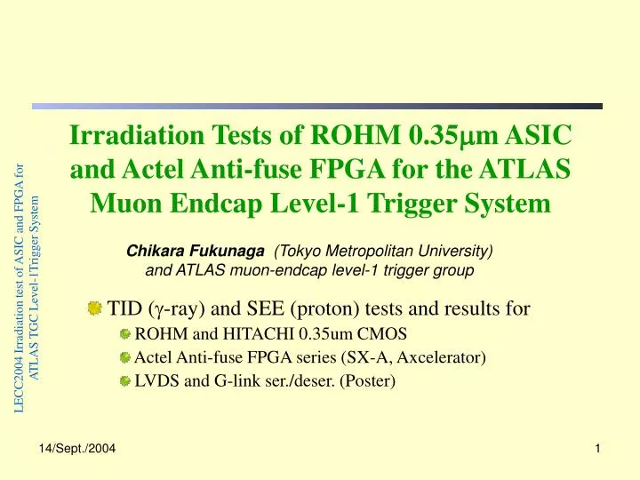
Irradiation Tests of ROHM 0.35 m m ASIC and Actel Anti-fuse FPGA for the ATLAS Muon Endcap Level-1 Trigger System. Chikara Fukunaga (Tokyo Metropolitan University) and ATLAS muon-endcap level-1 trigger group. TID ( g -ray) and SEE (proton) tests and results for ROHM and HITACHI 0.35um CMOS

E N D
Irradiation Tests of ROHM 0.35mm ASICand Actel Anti-fuse FPGA for the ATLAS Muon Endcap Level-1 Trigger System Chikara Fukunaga (Tokyo Metropolitan University) and ATLAS muon-endcap level-1 trigger group TID (g-ray) and SEE (proton) tests and results for ROHM and HITACHI 0.35um CMOS Actel Anti-fuse FPGA series (SX-A, Axcelerator) LVDS and G-link ser./deser. (Poster) LECC2004 Irradiation test of ASIC and FPGA for ATLAS TGC Level-1Trigger System
Introduction • Most of the ATLAS Endcap Muon Level-1 system will be installed in the detector (On-detector part). • Various trigger and readout circuits have been realized with (Three) ASIC chips. • Subsidiary circuits are implemented in FPGA chips. • The devices must be hard or tolerant for irradiation of 10 years. This must be confirmed with tests of • the ionizing damage (Total Ionizing Dose; TID) with g-ray • the Single Event Effects (SEE) with proton beam (> 60MeV) LECC2004 Irradiation test of ASIC and FPGA for ATLAS TGC Level-1Trigger System
ATLAS Muon Endcap Level-1 System • Thin Gap chambers (TGC) are used to detect muons in the endcap regions (1.05 h 2.70) • Hit (on/off) signals of Total 300k channels are processed in the vicinity of the chambers LECC2004 Irradiation test of ASIC and FPGA for ATLAS TGC Level-1Trigger System
Level-1 Trigger/Readout System • Two on-detector parts and off-detector part • On-detector parts • PS-board • Hi-pt and Star Switch (SSW) (VME) Crate PS-Board LECC2004 Irradiation test of ASIC and FPGA for ATLAS TGC Level-1Trigger System
Devices under Test • Custom ICs (8 types with 4 technologies) • PP (Patch Panel) ASIC0.35um CMOS ROHM • Variable Delay with PLL, LVDS to CMOS, BCID, Test pulse Gen. • SLB (SLave Board) ASIC0.35um CMOS ROHM • Low-pT coincidence matrices, Level-1 buffer+ Derandomizer • High-pT (Hi-pT) ASIC0.35um HITACHI GA • Hi-pT coincidence matrices • Simple FPGA Actel Anti-fuse SX-A • JRC (PS board), HSC, VME protocol • FPGA with embeddded memory Actel Anti-fuse Axcelerator • SSW Transmitter/Receiver • Serial Link IC (LVDS and G-link serdeser) LECC2004 Irradiation test of ASIC and FPGA for ATLAS TGC Level-1Trigger System
Radiation Environment TotalHadron (>20MeV) :/cm2/year 1.4-2.8x10¹⁰ hadrons/cm2/10year Ionizing Dose: Gy/year 2-3Gy/10year → 140-210Gy/10year (with Safety Factor:70) TGCElectronics TGCElectronics LECC2004 Irradiation test of ASIC and FPGA for ATLAS TGC Level-1Trigger System Interaction Point Interaction Point
Control Area Meas.Room TID test (g-ray irradiation) • Evaluation of Total Ionization Dose using g-ray from 60Co • A DUT (chip) is mounted on a PC board. • The board is applied with voltage and input signals • Irradiated 300Gy and more • Typically 4 samples/DUT • Icc or Frequency versus Abosrbed dose (time) has been evaluated LECC2004 Irradiation test of ASIC and FPGA for ATLAS TGC Level-1Trigger System RCNST lab. At Univ. of Tokyo
0.35mm ROHM CMOS full custom chip (PP, SLB) PP ASIC VCON(V) of PLL circuit for variable delay Special Made Ring Oscillator TID test results CMOS ROHM 0.35mm LECC2004 Irradiation test of ASIC and FPGA for ATLAS TGC Level-1Trigger System
TID test result CMOS Hitachi 0.35mm Gate Array (Hi-pT ASIC) • Hi-pT ASIC TID test LECC2004 Irradiation test of ASIC and FPGA for ATLAS TGC Level-1Trigger System
SX-A series Axcelerator series (embedded memory) Actel Anti-fuse FPGA series(Ring Oscillator Circuit) Core Logic I/O Cell LECC2004 Irradiation test of ASIC and FPGA for ATLAS TGC Level-1Trigger System
Single Event Effect Test: Proton 70MeV • SEE : Radiation induced bit flip (soft&hard) • If we know sSEE for a chip experimentally, we can predict SEE rate with SEE rate = sSEE x Nbits x SRLsee x SFsim LECC2004 Irradiation test of ASIC and FPGA for ATLAS TGC Level-1Trigger System
SEE test experiment at Tohoku Univ. • 70 MeV proton beam at Tohoku University Cyclotron (CYRIC) laboratory • Proton Intensity & beam profile were determined with dosimetry measurement of Cu foils (0.1mm) attached in front of DUT LECC2004 Irradiation test of ASIC and FPGA for ATLAS TGC Level-1Trigger System
Majority Logic SEE Test results: ASIC • sSEE for ROHM 0.35mm chips for PP, SLB: • A special IC was made (4bit shift registers) • sSEE for HITACHI 0.35mm GA • JTAG Boundary Scan reg. • Results: Soft SEE (No hard SEE observed) LECC2004 Irradiation test of ASIC and FPGA for ATLAS TGC Level-1Trigger System w/o majority Logic: It is installed in all the bits in chips
SEE test results: Actel Anti-fuse FPGA • A54SX-A series: 256 stage 4-bit Shift register • No SEE error has been observed with proton fluence of 2.6x10¹²proton/cm2 • sSEE < 1.5x10⁻¹⁵(1/cm2/bit) • Axcelerator AX250 series • 345 stage 4-bit Shift registers in R-CELL (FF-cell) • 32 SEE with proton fluence of 1.4x10¹²proton/cm2 • sSEE = 1.6x10⁻¹⁴ (1/cm2/bit) • 54Kbit embedded memory (dual port type) • 3869 SEE • sSEE = 4.9x10⁻¹⁴ (1/cm2/bit) Soft SEE only,No Hard SEE LECC2004 Irradiation test of ASIC and FPGA for ATLAS TGC Level-1Trigger System SEE rate for Actel FPGAs in whole system/day <2 Majority logic will be installed also
15m LVDS serializer/deserializer • LVDS serializer and deserializer candidates • NS:DS65LV1023/1024 • TI:SN65LV1023/1224 • Connected with UTP cat. 5 cable (15m) LECC2004 Irradiation test of ASIC and FPGA for ATLAS TGC Level-1Trigger System
TID test up to 1600Gy NS:Icc vs. Dose:No significant Icc increase TI: Icc vs. Dose:↓ SEE test TID and SEE tests of LVDS ser/deser LECC2004 Irradiation test of ASIC and FPGA for ATLAS TGC Level-1Trigger System Broken TI chip will be fine if dose < 1000Gy
Summary • ATLAS TGC electronics • TID 140-200Gy/10 years & SEE ~2x1010cm2/10years • g-irradiation (TID) Test • ASIC/Actel anti-fuse FPGA chips have no problem up to ~1000Gy • Proton 70MeV irradiation (SEE) Test • Measurement of sSEE for Soft SEE: rate will be expected as very low • No destructive (hard) SEE like Latch-up has been observed. • Link (LVDS, G-link) components See in detail our Poster presented in this workshop LECC2004 Irradiation test of ASIC and FPGA for ATLAS TGC Level-1Trigger System