Download
1 / 28
290 likes | 505 Views
Frank Laboratory of Neutron Physics Joint Institute for Nuclear Research. RESIDUAL STRESS STUDIES IN ELECTRON AND LASER BEAM WELDING USING NEUTRON DIFFRACTION. Gizo Bokuchava 1 , Peter Petrov 2 , Igor Papushkin 1 , Andrew Venter 2

E N D
Frank Laboratory of Neutron Physics Joint Institute for Nuclear Research RESIDUAL STRESS STUDIES IN ELECTRON AND LASER BEAM WELDING USING NEUTRON DIFFRACTION • Gizo Bokuchava1, Peter Petrov2, Igor Papushkin1, Andrew Venter2 1 Frank Laboratory of Neutron Physics, Joint Institute for Nuclear Research, Dubna, Russia • 2 Institute of Electronics of Bulgarian Academy of Sciences, Sofia, Bulgaria 3 South African Nuclear Energy Corp. NECSA Ltd., Pretoria, South Africa Third National Conference with International participation “Materials Science, Hydro- and Aerodynamics and National Security ’2013”, October 24 - 25, 2013, Sofia, Bulgaria
Joint Institute for Nuclear Research - JINR 7 Research Laboratories and University Centre VBLHEP Veksler and Baldin Laboratory of High Energy Physics DLNP Dzhelepov Laboratory of Nuclear Problems BLTP Bogoliubov Laboratory of Theoretical Physics FLNP Frank Laboratory of Neutron Physics FLNR Flerov Laboratory of Nuclear Reactions LIT Laboratory of Information Technologies LRB Laboratory of Radiation Biology UC University Centre
IBR-2 pulsed reactor in FLNP JINR Neutron spectrometers at the IBR-2 pulsed reactor
Residual stress study by neutron diffraction Bragg’s law: 2·d·sin = = 2·d·sin = 2·tμs/(505.556·L) (TOF-method) a/a0= (d – d0)/d0- diffraction peak shift (lattice strain) = E·l/l = E· (d – d0)/d0 (Hook’s law) Incident neutron beam Sample Scattering (gauge) volume Diffraction peak shift at stress value=20 MPa and=200 MPa(steel, E=200 GPa) observed at diffractometer with resolution level of R≈0.001 Layout of experimentfor residual stress study in bulk sample
Microstructure analysis:coherent domain size, macro- and microstress, texture -Fe (Im3m, a=2.8664 Å), FSD (IBR-2, Dubna) Peak intensity --> crystal structure and texture Peak position -->mean lattice parameter Peak width --> coherent domain size and microstrain
Diffraction peak broadening effects W2 = W02 + C1d2 + C2d4 – diffraction peak width C1 = <ε>2– variance of d (microstrain) C2~ 1/<D>2– crystallite size W0– instrument resolution function Resolution function (standard Al2O3 sample) andpeak broadening effect due to crystallite size (dispersiveNi) Peak broadening due to microstrain
FSD – Fourier Stress Diffractometer at the IBR-2 pulsed reactor (JINR, Dubna)
High-resolution Fourier diffractometry for long pulse neutron source IBR-2 is a long-pulse neutron source. Δt≈300 μs, R ≈ 0.01 (L=25 m, d=2 Å) Objective: R ≤ 0.001 (L=25 m, d=2 Å) Fast Fourier chopper F-chopper parameters (FSD): N=1024 Vmax=6000 rpm Ωmax=102.4 kHz Δt0≈10 μs 7.5 kW motor
Fourier chopper Slit width 0.7 mm Stator Rotor Transmission function Binary signals
FSD diffractometer Backscattering detector Neutron guide Sample position 90º-detector
FSD detector system: combined geometrical and electronic focusing 6Li glass backscattering detector assembling on FSD 90º-detectorsystembased on ZnS(Ag) scintillator with wavelength-shifting fibers
Multisectional radial collimator on FSD (Δx=2mm) Gauge volume = 2 mm, Number of slits = 160, Length = 600 mm, Focus distance = 350 mm
Measured spectra and resolution function FSD resolution function measured on -Fe powder at maximal Fourier chopper speed Vmax=6000 rpm Part of neutron diffraction pattern from the -Fe standard sample measured on FSD in high-resolution mode by BS- (top) and 90 (bottom) detectors. Experimental points, profile calculated by the Rietveld method and difference curve are shown.
Diffraction peak shape and pulse width Effective neutron pulse width dependence versus maximal Fourier chopper speed Diffraction peak shape dependence versus maximal Fourier chopper speed
Sample environment Mirror furnaceMF-2000: power- 1 kWt max. temperature- 1000 C HUBER goniometers
Sample environment Stress rig LM-20 max. load- 20 kN max. temperature - 800 ºС Stress rig TIRAtest: max. load- 60 kN
Welded Charpy test specimens Problem Changes in the material properties due to neutron irradiation are monitored by means of surveillance programs. Specimen’s surveillance programs for reactor pressure vessel (RPV) materials are among the most important parts of inspection programs that are necessary for realistic evaluation of RPV lifetime. • In nuclear power plants (NPP), Charpy specimens are used to evaluate the RPV embrittlement. However, it is necessary to obtain more statistics on the pressure vessel embrittlement (especially for older NPP's). Reconstitution technology allows performing additional fracture toughness tests on a limited amount of available material and can contribute to a better characterization of the material and, therefore, to a better evaluation of the embrittlement degree of RPV steel due to neutron irradiation. • Objective • The aim of this work was the experimental determination of residual stress distribution in the surveillance Charpy specimens reconstituted by various welding techniques using high resolution neutron diffraction.
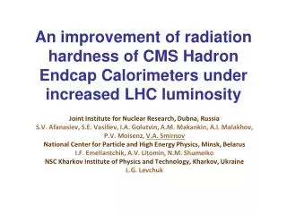
Welded Charpy test specimens Collaboration: Institute of Electronics of Bulgarian Academy of Sciences (Sofia, Bulgaria) Frank Laboratory of Neutron Physics, JINR (Dubna, Russia) • South African Nuclear Energy Corp. NECSA Ltd. (Pretoria, South Africa) Scheme of the methods applied for reconstitution of Charpy and CT test specimens EBW procedure for reconstitution of Charpy specimens Scheme of the electron beam welding process Studied Charpy specimens: low alloyed steel (wt%): 0.18% C; 0.35% Si; 0.012% P; 0.013% S; 0.32% Cr; 0.58% Mn; 0.72% Ni; 0.13% Cu; 0.61% Mo; 0.1% Cu. EBW parameters: accelerat. voltage U=60kV; beam current I=50 mA, welding speed V=1 cm/s, focusing lens - specimen distance D0=38cm.
Studied samples & experimental setup • Charpy test specimens (with electron and laser beam welding) • Steel plate with laser beam welding Charpy - EBW Typical shape of EBW weld seam and heat affected zone (HAZ) at U=60kV Charpy - LBW εy Steel plate - LBW LBW plate: S355J2+N steel (wt%): 0.14% C; 0.35% Si; 1.38% Mn; 0.012% P; 0.004% S; 0.024% Cr; 0.002% Mo; 0.004% V; 0.024% Cu; 0.011% Ni; 0.038% Al; 0.0033% N; 0.04% Nb.
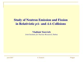
Experimental results: diffraction spectra Charpy - EBW 3D plot and map of the neutron diffraction pattern near (211) reflection during x-scan Microhardness distributions for EBW specimen along the weld depth: Section I - 8 mm from surface, Section II - 5 mm from surface, Section III - 2 mm from surface.
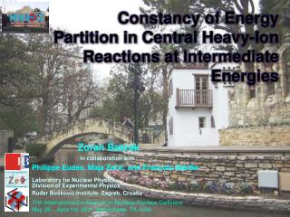
Experimental results: strain & stress Residual strain (top) and stress (bottom) in test Charpy samples reconstituted by electron (EBW) and laser (LBW)beam welding
Experimental results: peak broadening & microstrain Diffraction peak width parameter (top) and estimated microstrain (bottom) in test Charpy samples reconstituted by electron (EBW) and laser (LBW)beam welding
Experimental results: steel plate with laser beam welding εx εy The layout of experiment for residual stress study in steel plate with LBW on FSD neutron diffractometer Residual stress (top) and microstrain (bottom) in steel plate with laser beam welding
Conclusions • The welded Charpy specimens, recovered by electron and laser beam welding, were investigated by neutron diffraction. • The residual stress and microstress level is significantly higher for LBW specimen as compared to the EBW one. The same result was obtained for steel plate with laser beam welding. This confirms well known fact that among all the methods (arc welding, EBW, LBW) the electron beam welding method results in lowest level of residual stresses in welds. • Diffraction peak broadening is rather significant and is well pronounced at the weld seams locations, which makes it possible to reliably determine the microstrain level in the material. • Anisotropic character of the peak broadening effect indicates its dislocation nature. Thus the evaluation of dislocation density from diffraction peak broadening effect is possible too.
NEUTRONS FOR USERS Principles of FLNP user policy The IBR-2 pulsed reactor is a user facility that provides neutron measurement capabilities to researchers from academia and industry. The access to experiments on the IBR-2 spectrometers for all users is granted on the basis of applications for beamtime. The proposals for experiments are peer-reviewed and rated by Expert Committees and beamtime is allocated on the basis of scientific merit of the proposal. Scientists from any country of the world can apply for beamtimefree of charge. Researchers from JINR member states get additional financial support. The next deadline for proposal submission is November 1, 2013. Frank Laboratory of Neutron Physics (FLNP): http://flnp.jinr.ru IBR-2 reactor user’s club: http://ibr-2.jinr.ru