Download
1 / 38
400 likes | 698 Views
PNEUMATICS AND PRESSURIZATION. Brake Deice Bleed Air Warning System Rudder Boost System. Pressurization Controller Pressurization Safety Valve. BLEED AIR PNEUMATIC AND VACUUM SYSTEMS.

E N D
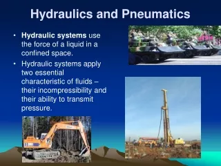
Brake Deice Bleed Air Warning System Rudder Boost System Pressurization Controller Pressurization Safety Valve BLEED AIR PNEUMATIC AND VACUUM SYSTEMS Pneumatic air is utility air used by various systems in the aircraft. It originates from the P3 section of the engine, is routed through firewall shutoff valves and regulated to 18 PSI. Pneumatic air supplies pneumatic pressure and vacuum for the following systems: PressureVacuum • De-Ice Boots
PNEUMATIC SYSTEM
General Information Bleed air comes off of each engine and is brought back to the fire seal. Right after the fire seal and before the flow pack, we tap off the little P3. Air passes through a N.O valve (power required to close it). The air then passes through a one way check valve installed in the bleed air line which ensures adequate air supply during single engine operation by preventing air from escaping back into the compressor of the inoperative engine. Next both engines P3 air joins at a T fitting and goes to a regulator that steps the pressure down from 120 to 18 PSI.
BRAKE DEICE SYSTEM
Brake Deice • First system to use the pneumatic air • System consists of: • Plumbing • Two solenoid operated valves operated by Brake Deice switch • Distributor manifold on each main gear • Electrical circuit containing a time delay PCB
Brake Deice • If the aircraft takes off with the brake deice control switch on, a circuit is completed between uplock switch and timing circuit • Solenoid closed after 10 minutes • Can’t activate till gear cycled down • If operation does not auto terminate after 10 minutes; turn brake Deice switch-OFF • Don’t operate brake deice > 15 degrees C • >85% N1 required to operate brake deice and surface deice at the same time
BLEED AIR WARNING SYSTEM
Bleed Air Warning System • The engine uses 25% of air for combustion and the other 75% to cool engine and drive pressurization and pneumatic systems • System provides for visual indication in the cockpit of a ruptured bleed air line • Bleed air lines are accompanied / paralleled by bleed air warning lines of plastic (polyflow) tubing from the engines to the cabin
Bleed air warning lines are plugged and have an internal pressure of 2 psi. • If a bleed air line fails, escaping hot air wil melt the paralleling warning line. • Resulting drop in pressure (1 psi) will actuate a pressure switch and illuminate the L or R BL AIR FAIL warning light • Steady illumination of the warning light indicates a possible ruptured bleed air line aft of the firewall. Follow procedure in checklist / operator’s manual.
Bleed Air System Emergency Procedures / Knowledge Check • Procedure: Brake Deice switch-off, ITT and TQE monitor (note readings),Bleed Air switch- OFF, Cabin Pressurization-check • Break in big P3 inside vessel will not result in change in torque or ITT. • Break in little P3 will always result in drop in torque and rise in ITT. • Break in P3 forward of firewall = drop in torque and rise in ITT but no warning light. Is the paint blistering?
RUDDER BOOST SYSTEM
Rudder Boost • Aids pilot in maintaining directional control in the event of engine failure • Differential pressure valve accepts high pressure bleed air pressure from each engine • If pressure differential reaches preset tolerance, rudder boosting servos activate cables to compensate for asymmetrical thrust • System controlled by RUDDER BOOST switch and tested during run-up
Rudder Boost Continued….. • Moving either bleed air valve switch to PNEU & ENVIR off will disengage the system, however, note that both switches must be in OPEN for system to operate correctly (environmental switches complete electrical circuit required for activation) • Discuss unscheduled Rudder Boost Activation Emergency Procedure
SURFACE DEICE SYSTEM
Surface De Ice • System removes ice accumulation from leading edges of the wing and horizontal stabilizer by alternately inflating and deflating boots. • The inflation and deflation phases are controlled by a surface deice distributor valve and automatic timer • Actuated by three position switch; MANUAL – OFF - SINGLE CYCLE AUTO • Spring loaded to OFF
Surface De Ice Continued… • Pressure regulated bleed air supplies pressure to inflate the boots. • A venturi ejector, also operated by bleed air, creates vacuum to deflate boots and hold them down while not in use. • Single Cycle Auto – via distributor – inflates wing boots for 6 seconds, timer deflates wing boots and 4 second inflation begins on horizontal stabilizer boots. When deflated, cycle complete.
Surface De Ice Continued… • Manual position; all boots inflate simultaneously and remain inflated till switch released, then go into vacuum hold-down condition until actuated again. • Use of system below –40 degrees C can cause permanent damage to the boots • Allow minimum ½ inch of ice to form before attempting ice removal. • (Discuss SOP requirements)
Vacuum System • Vacuum is created by pneumatic bleed air flowing through the venturi ejector mounted beneath the cabin floor. The venturi effect creates a vacuum as bleed air passes through the venturi cone. The vacuum regulator valve maintains a constant vacuum level in the system by bleeding in ambient air through the vacuum regulator filter.
Vacuum System Cont… • The surface deice system uses vacuum as previously discussed. • The pressurization system uses vacuum directly to operate the safety valve to depressurize the cabin. The pressurization controller uses vacuum to control the cabin pressure outflow valve. Each will be covered in discussing the Pressurization System.
Pressurization BACKGROUND Turbine aircraft are more efficient in terms of True airspeed and fuel flow at higher altitudes. The crew needs either supplemental oxygen or a pressurized cabin to operate at these altitudes because atmospheric pressure decreases with an increase in altitude. Pressurization is desirable in an airplane because it allows the altitude of the cabin to be lower than the altitude of the airplane.
DEFINITION’S CONT… • Pressure vessel means the portion of the aircraft which is designed to withstand the pressure differential. The pressure vessel extends from a forward pressure bulkhead between the cockpit and nose section to a rear or aft pressure bulkhead just behind the baggage compartment, with exterior skins making up the outer seal. Side windows are of a round design for maximum strength. All cables, wire bundles, and plumbing passing through the pressure vessel boundaries are sealed to reduce leaks.
PRESSURIZATION REQT’S To have a pressurization system we must have an air source to increase the pressure inside the pressure vessel, a means to regulate the pressure, and an emergency relief system. The pressurization system in the C-12 pumps engine bleed air in and we control the rate it leaks out.
AIR DELIVERY SYSTEM Engine bleed air is ducted from the last compressor stage (station 3) of each engine. This P3 air line is routed to the electronic flowcontrol unit (sometimes called the flow pack) mounted at the firewall. The flow control unit regulates the mixture of engine bleed air with ambient air from the cowling intake.
Air Delivery Cont….. • Pilot controls inflow with ENVIRO & PNEU BLEED AIR switches. ON = Valve in Flow Pack open; air allowed into duct system • Heated air may be retained for heating, or cooled through air-to-air heat exchanger on the way to cabin • Check valve installed in environmental (Big P3) lines to prevent pressure loss in the event of engine failure • Air flows through mixing plenum to ducts for windshield defrost, flight compartment air, and floor outlets for cabin air.
ELECTRONIC FLOW CONTROL UNIT • Controls flow of ambient and bleed air as a function of atmospheric temperature, for cabin heating and pressurization. • Regulates the inflow of air into the pressure vessel • Flow control unit attempts to always provide a relatively constant inflow. Advantage of electronic flow pack is that it can maintain scheduled pressurization even with power levers at idle
FLOW CONTROL UNIT CONT… • After T/O, the main landing gear safety switch prevents pressure bumps by allowing left ambient air valve to open first. Through a 4-6 second time delay, the right ambient air valve will open. • As aircraft climbs and temperature decreases, ambient flow valve closes incrementally to maintain sufficient heating until 0 degrees Celcius when it becomes completely closed.
PRESSURIZATION CONTROL SYSTEM AND COMPONENTS5 Primary Components: • Controller to select cabin altitude and rate of climb/descent • System switch to select pressurization, de-pressurization, or test of the system • Indicators to inform the flight crew of system performance • An outflow valve to control cabin altitude • A safety valve to protect against over-pressurization and to provide emergency de-pressurization
Pressurization Control Cont… • Pressurization Controller maintains selected cabin altitude dialed into it by adjusting flow of air out of the pressure vessel through the outflow valve. • Rate control knob regulates the rate at which the cabin pressure ascends or descends to the selected altitude. • System indicator: Long needle = cabin altitude Short needle = pressure differential • Maximum differential is 6.5 +/- .1 PSI
OUTFLOW VALVE FUNCTIONS: • Modulates. The outflow valve modulates to give us the desired pressure inside the pressure vessel; we are controlling the pressure going out. The valve is opened or closed by the pressure controller using vacuum. • Negative Differential Relief. (Greater pressure outside the airplane than inside) If it were to happen, the outside pressure will push on the negative relief diaphragm and relieve the negative pressure.
SAFETY VALVE • Safety valve prevents pressurization on the ground, does nothing during normal pressurized flight. Primary Functions: • Dump. Pilot opens the safety valve by placing system control switch to DUMP. • Maximum Pressure Relief. Safety valve senses cabin differential. Relief valve set to trigger at 6.5 PSI will guard against over-pressurization. If exceeded, valve opens and vents excessive pressure outside the pressure vessel. Once within limits, valve closes. • Negative Differential Relief. Safety valve will relieve negative pressure the same way as the outflow valve.
Before Engine Start (Engines Off) When DC electrical power is applied to the aircraft , the pressurization system receives power. Power is routed through the PRESS CONT CB, the pressurization system switch, the left main landing gear safety switch to the N.C. Dump Solenoid and N.O Preset Solenoid. When these solenoids receive power the Dump Solenoid opens and the Preset Solenoid closes. Since the engines are not running there is no environmental air at this point.
Engines running prior to T/O Bleed Air Valves Open After the engines are started there is P3 air for both Pressurization and vacuum. The pressurization or environmental air enters the Pressure vessel through the duct system as depicted as a red arrow in the upper left hand corner. Vacuum is blocked from the pressure controller by the closed preset solenoid. This keeps the outflow valve closed. Since the dump solenoid is open, Vacuum reaches the safety valve and opens it.. The environmental air is ported outside of the pressure vessel through the safety valve preventing the aircraft from pressurizing on the ground.
Pressurization Test To test pressurization, set the cabin altitude 500 feet below field pressure altitude on the pressure controller. Then place the cabin pressure control switch to TEST. Electricity is removed from both solenoids causing the preset solenoid to open and the dump solenoid to close. Since we’re asking for a lower cabin altitude it is necessary to increase the cabin pressure. Since environmental air is continuing to enter the pressure vessel and the outflow valve and the safety valve remains closed, the cabin pressure increases as the system descends the cabin to the lower altitude. This is shown as a descent on the cabin controller rate indicator. This verifiesthat the pressurization system is working correctly.
After Takeoff (Normal Pressurization) When the aircraft takes off, the left main landing gear squat switch de-energizes the preset solenoid open and the dump solenoid closed, positioning them to their normal flight modes. As the airplane climbs, the controller modulates the outflow valve based on commands from the rate control chamber. By regulating how much vacuum is applied to the rate chamber in the controller, the outflow valve is positioned to yield the desired rate of climb. If the pilot increases the rate of climb, the leak in the lower chamber is increased from the upper chamber causing an increase in pressure in the upper chamber which moves the needle valve down allowing more vacuum to the outflow valve. More vacuum causes the outflow valve to open slightly more causing an increase in the rate of climb.
Ram Air Door Pressurization Dump (Airborne) > 12,500 Will illuminate If the flight crew deems it necessary to de-pressurize the cabin because of some emergency, the DUMP position on the system select switch will energize the dump solenoid and de-energize the preset solenoid. When the dump solenoid is energized vacuum reaches the safety valve and pulls it open, rapidly de-pressurizing the cabin. A small solenoid operated door is located in the right side forward fuselage area ahead of the copilots feet. Commonly called the ram air door, it is held tightly closed by a solenoid that receives 28 VDC through the PRESS detent of the system control switch. When the switch is moved to the DUMP position , the solenoid is de-energized and the door is opened by ram air pressure.
DESCENT / ARRIVAL On descent for landing, schedule the controller to depressurize the cabin 500 feet above landing airport field elevation; this ensures cabin will not dump when the left main landing gear safety switch activates. When the weight of the airplane activates the safety switch, the pressurization again reverts to the ground mode. The preset solenoid is energized closed and regulated vacuum for the controller is off. The dump solenoid is energized open and the safety valve is held open with vacuum. The ram air door solenoid remains energized and closed.