Download
1 / 9
90 likes | 219 Views
LLRF Upgrade Commissioning Results Run 10 Start-Up. RHIC Time Meeting K. Smith, 01/12/2010. M. Harvey, T. Hayes, F. Severino, S. Yuan, R. DiFranco, J. Juarez A. Zaltsman, J. M. Brennan, M. Blaskiewicz, J. Butler, S. Polizzo, L. Hoff, K. Unger, P. Oddo.

E N D
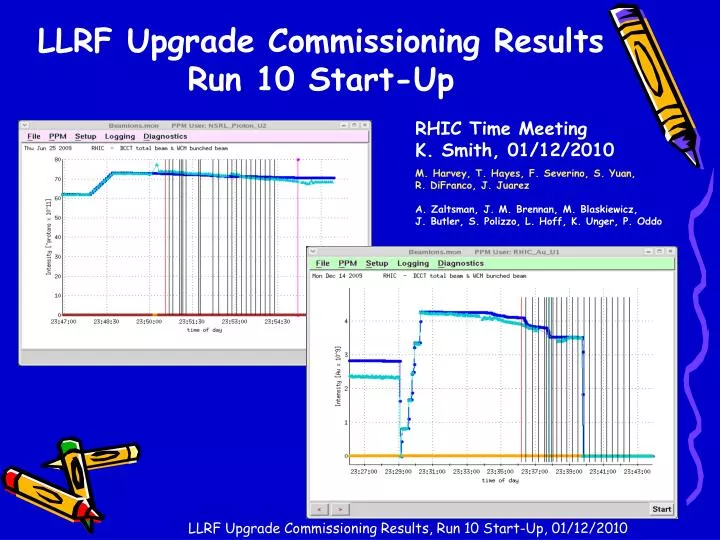
LLRF Upgrade Commissioning Results Run 10 Start-Up RHIC TimeMeeting K. Smith, 01/12/2010 M. Harvey, T. Hayes, F. Severino, S. Yuan, R. DiFranco, J. Juarez A. Zaltsman, J. M. Brennan, M. Blaskiewicz, J. Butler, S. Polizzo, L. Hoff, K. Unger, P. Oddo LLRF Upgrade Commissioning Results, Run 10 Start-Up, 01/12/2010
Refresher: Goal of the LLRF Upgrade • Design a stand alone, generic, modular digital controller architecture which can be configured to satisfy all of the LLRF control demands we currently have, and which will be supportable and upgradeable into the foreseeable future. It has potential applicability to many tasks … • Integrate seamlessly into existing controls infrastructure, be easy to deploy, provide access to all relevant control parameters, provide vastly improved diagnostic data capabilities, and supportremote reconfiguration of firmware and software. • LLRF “Controller” (Appendix A) • Original “LLRF Upgrade” scope was simply to replace the RHIC cfe-4a-rfb2 and cfe-4a-rfy2 VME crates. So, we’ve finally gotten there. Lots of potential moving forward … LLRF Upgrade Commissioning Results, Run 10 Start-Up, 01/12/2010
Results From Run 10 Start-Up • Initial Commissioning of the RHIC LLRF System has been completed. • ATR Synchro and Injection Cogging • Workaround for 4 transfers, firmware fix for injection cogging to be installed and tested Wednesday • LLRF Feedback Loops • BTB Phase Loop, Radial Loop, Ring to Ring Synchro Loop, Brho Loop all functioning.Fine tuning of all loop parameters to continue as possible. • Collision Cogging • Auto and manual cogging functioning. Some issues with name changes in loop status causing confusion. • Rebucketing • Performing extremely well. Readily re-tuned to accommodate variable beam loading. • Quad Mode Damping • Software ready for test. Awaiting hardware installation. Low priority. • System development efforts continue unabated. • Hardware, firmware and software configurations are changing daily to address issues as they are encountered. LLRF Upgrade Commissioning Results, Run 10 Start-Up, 01/12/2010
What Replaces What? O In With The New … Out With The Old … LLRF Upgrade Commissioning Results, Run 10 Start-Up, 01/12/2010
One Example of a New System Benefit • System Flexibility: Initial Install and Day 1 Commissioning • The master timing and data distribution chassis (the “Update Link Master” or “ULM”) would not decode external events – kinda critical. Discovered around midnight. Most unique piece of the system. • In 1 1/2 hours, had problem diagnosed, randomly selected developmentchassis configured and tested, installed and operational as the new ULM. • Dec-06-2009 00:12 (1 edit): We are not decoding external events for some reason. TPH is testing in lab in 911 on identical configuration to see how that behaves there. We continue trying to diagnose out here. -KSS Dec-06-2009 00:31 (2 edits): Chassis in lab appears to be functioning as expected. TPH is bringing chassis to 1004A for install. We're trying some last minute stuff in the meanwhile (power cycles, etc.). -KSS Dec-06-2009 00:39: Doing some comparison testing between 4a-rfllb1 and 4a-rfulm. 4a-rfllb1 appears healthy. Checking event connections via ecto. -KSS æDec-06-2009 01:05: Swapped in 911B lab ULM chassis (S/N 0006) for S/N 0005. Bringing up, configuring and preparing to test. -KSS Dec-06-2009 01:09: FFS is configuring the MAC address, IP address, etc. so we can boot new chassis. -KSS Dec-06-2009 01:11: Chassis boots and appears to be decoding rhic event link (per embedded V202). Beginning to bring everything back up. This will take some time. -KSS • This worked because the system is designed around a common hardware platform, which we then configure via software, firmware and daughter hardware to provide desired functionality. LLRF Upgrade Commissioning Results, Run 10 Start-Up, 01/12/2010
Examples of New System Growing Pains • FEC “Hangs” • Altho our embedded FECs function mostly transparently, as any other RHIC FEC, they are not identical. We have a continuing issue with the most heavily loaded FECs “seizing” . LTH, FFS and PH are using both the operational FECs and development FECs in the LLRF lab to diagnose. • Blue BTB Phase Detector peculiar fondness for resetting to near 180 degrees, instead of 0 degrees. • If not caught prior to a ramp, will cause a phase rollover shortly into the ramp, causing a massive loop transient, beam loss and … • ADT serving as the work around for this while problem is diagnosed. • Injection Cogging Issue • Initially unable to inject full AGS cycle (4 bunches) into RHIC. • Work around implemented in software, in addition to modifying the AGS cycle time to allow for 150ms per transfer instead of 100ms. • Firmware fix under test, with install planned for Wednesday maintenance. • Timing Shifts • We have a known issue which results in the possibility of a non-deterministic reset between certain RF synthesizers. Exacerbated by the mysterious (ESD related?) reconfigs of rfllb1 and rflly1 crates. • Seems to have been helped by disconnecting wiring from front panel RESET and RECONFIG push buttons. • Several related fixes in the works. LLRF Upgrade Commissioning Results, Run 10 Start-Up, 01/12/2010
The Summary • We think the commissioning of the upgraded LLRF during the start-up of RHIC Run 10 has gone remarkably well. • The vast majority of the necessary functionality has worked on the first attempt. • See the “Results” slide. • The system certainly has its share of bugs, idiosychracies, etc., but what hasn’t worked or only sorta works hasn’t proven to be a show stopper. • Work arounds and fixes for our known issues. • System is demonstrating its flexibility. • Recall the Update Link Master situation on the “New System Benefits” slide. • System development is on-going. We expect to continue to make changes to improve the system during the course of the run. • Moving forward, we expect to begin realizing the full potential of the platform: more RHIC development (LLRF, HLRF, Spin Flipper, ?), EBIS, ERL, AGS, Booster … • We appreciate the amount of machine development time allocated to us to get this commissioning effort done. I’m sure we’ll come asking for more. LLRF Upgrade Commissioning Results, Run 10 Start-Up, 01/12/2010
Thanks … MCR and AP have been extremely cooperative throughout the commissioning effort. Extra thanks to V. Schoefer and G. Marr for their efforts and close cooperation. L. Hoff and K. Unger for all the FEC development support. J. Butler for constant all hours support in 1004a. J.M. Brennan and M. Blaskiewicz for always having the answers. C-AD Management for providing the resources we needed to get this done. Last but not least, a very sincere thank you to the boss, Alex Zaltsman, who provided unflinching support for this effort from its inception. LLRF Upgrade Commissioning Results, Run 10 Start-Up, 01/12/2010
Appendix A: “Controllers” ??? • Primary LLRF Hardware Development Effort: The LLRF Controller • A Controller is a configurable, universal digital signal processing platform, the basic building block from which a complete LLRF system is built. • “System Controller”: Frequency program, beam control loops, synchro loops, damping, adaptive loops (cycle to cycle feedback), etc. • “Cavity Controller”: Individual cavity amplitude, phase, tuning, control of other HLRF parameters. • A Controller is configured as needed from two major components: • “Controller” = “Carrier Board” + N “Daughter Cards” • Both the Carrier and Daughter designs are based on a common, powerful FPGA family, Xilinx Virtex-5. • Carrier Board • Stand alone control system interface. The C-AD Control System sees it as a standard FEC. Compatible with all Controls system infrastructure. • Daughter host platform, system power source, system status monitor, communication hub, data acquisition engine, update and controls link receiver. • Daughter Cards • Provide system specific functionality via data converters and processing horsepower. • All daughter modules reuse a common “back end” digital architecture providing the carrier interface and support for all standard daughter features (e.g. DDR2 SO-DIMM, FLASH, Power Converters …) • ADC, DAC, FPGA, DSP ... LLRF Upgrade Commissioning Results, Run 10 Start-Up, 01/12/2010