Download
1 / 23
290 likes | 1.01k Views
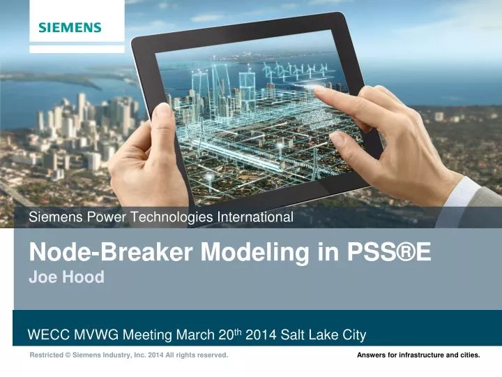
Siemens Power Technologies International. Node-Breaker Modeling in PSS®E Joe Hood. WECC MVWG Meeting March 20 th 2014 Salt Lake City. Node-breaker Modeling in PSS®E Key Points. Available in Version 34 Planned for Q3 this year Further integration with later minor releases

E N D
Siemens Power Technologies International Node-Breaker Modeling in PSS®EJoe Hood WECCMVWGMeeting March 20th 2014 Salt Lake City
Node-breaker Modeling in PSS®EKey Points • Available in Version 34 • Planned for Q3 this year • Further integration with later minor releases • Unobtrusive Implementation • There when you need it, but… • Out of the way when you don’t want it • Full Integration into SAV and RAW formats • New data records attached to end of RAW file • No changes needed to existing data records to add Node-breaker topology • Automatic Substation Node-breaker Topology Building • One-click process for building initial-pass topology directly from single line diagrambased on common arrangements (1 ½ breaker, double breaker, ring bus, etc.) • Substation Node-breaker single line diagrams drawn automatically
Big Picture Traditional Network Data SLDs Node-breaker Data Topology Processor API Scripts Internal Network Model Analysis Engines
PSS®E Node-Breaker Terminology Bus Branch Nodes Branch Substation Connection Devices
Substation/Node/Bus Mapping Substations Nodes Buses 1 ∞ ∞ 1 ∞ 1 Key: Sub ID Key: (Sub ID, Node ID) Key: Bus ID
Branch Mapping Bus I Node NI (I, J, CKT) Node NJ Bus J Branch/2-winding Connection Record: (I, J, CKT, NI, NJ) 3-winding Connection Record: (I, J, K, CKT, NI, NJ, NK)
Terminal Device Connection Mapping (I, MACHID) Node N1 Bus I Connection Record Format for All Device Types: (I, ID, NI)
Mapping Example Substation 1 1 (101, ‘1’) 5 2 3 6 101 4 (101, 102, ‘1’) 7 102 8 9 10
RAW Format Extension Substation Data Node Data Station Switching Device Data Branch/Two Winding Connection Data Three winding transformer Connections Load Connections Shunt Connections Machine Connections Switched shunt Connections
Load Connection Record(Representative of Terminal Device Connection Records)
RAW Example • 0 // Substations (I, STNAME, X, Y): • 1 'SUB 153' 1.0 1.0 • 0 // Nodes (SUBSTATION, BNODE, I, 'NODE NAME', STATUS): • 1 153 1 'SECTION 1 ' 1 • 1 153 2 'SECTION 2 ' 1 • 1 153 3 'SECTION 3 ' 1 • 1 153 4 'SECTION 4 ' 1 • 0 // Breakers (SUBSTATION, I, J, CKT, NAME, STATUS, NSTATUS, TYPE, X,...): • 1 1 2 '@1' 'BREAKER ' 1 1 0 0.00000 0.00010 0.0 0.0 0.0 • 1 2 3 '@1' 'BREAKER ' 1 1 0 0.00000 0.00010 0.0 0.0 0.0 • 1 3 4 '@1' 'BREAKER ' 1 1 0 0.00000 0.00010 0.0 0.0 0.0 • 1 4 1 '@1' 'BREAKER ' 1 1 0 0.00000 0.00010 0.0 0.0 0.0 • 0 // Branch Terminals (IBUS, JUBS, CKT, INODE, JNODE): • 153 154 '1 ' 2 1 • 153 154 '2 ' 3 2 • 153 3006 '1 ' 4 0 • 153 152 '1 ' 1 0
Substation Data Persistence • RAW File • Topology/Connectivity • Bus/Node Mappings • Switching Status • SubstationSLDs • Substation Layout • Annotations • Diagram Primitives (Drawings)
Node-breaker SLD Links Bus-branch SLD • Allows navigation between the two worlds • We’re still working on the proper visual design and user experience • What should a bus look like vs a Node? • Should double-clicking bus show • Node-breaker substation? Substation SLD
Managing Substation SLDs PSS®E File Data Manager PSS®E Substation SLD Repository Setup Master Directory for SLD Files • … Or just build substation diagrams on the fly on demand as needed. • Managing SLDs only necessary if you want to maintain a specific layout
Interacting with Node-breaker Model • Open/close breakers in SLDs • Edit data in network data grids • Manipulate via APIs • Soon to be incorporated in CON/MON/SUB syntax, RAS definitions, etc
Example APIs • # add/change substation data: • station_data(i, realar, name) • # add/change node data: • node_data(is, i, intgar, name) • # add/change switching device data: • station_swd_data(is, i, j, ckt, intarg, realar, name) • # build substation topology: • sbuildmodel(option, i) • # open beakers necessary to deenergize line • open_line_with_breakers(I, J, CKT)
Contact Joe HoodProduct Manager – PSS®ESiemens PTI Phone: +1 (803) 399-0563 Email: joseph.hood@siemens.com