Download
1 / 39
500 likes | 820 Views
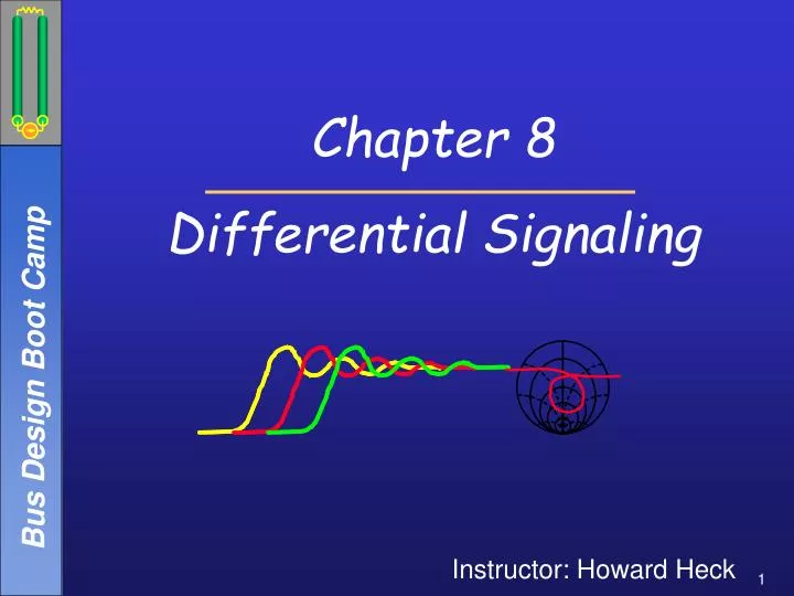
Chapter 8 Differential Signaling. Instructor: Howard Heck. Schedule. Day 1 Introduction – Bus design Overview Falconer 0.25 Transmission Line Fundamentals Leddige 2.0 Digital Timing Analysis Heck 2.0

E N D
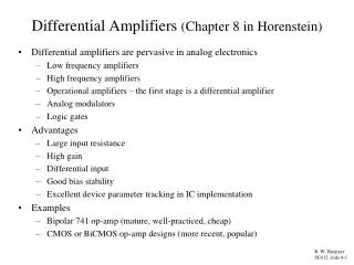
Chapter 8 Differential Signaling Instructor: Howard Heck
Schedule • Day 1 • Introduction – Bus design Overview Falconer 0.25 • Transmission Line Fundamentals Leddige 2.0 • Digital Timing Analysis Heck 2.0 • Crosstalk Falconer 2.0 • Non-ideal Interconnect Hall 2.0 • Day 2 • Connectors, Packages and Vias Mix 2.0 • NIRPS, SSO, Power Delivery Hall 2.0 • Differential Signaling Heck 2.0 • Buffer Modeling Nelson 2.0 • Day 3 • Introduction to network analysis Hall 2.0 • Equalization Overview Heck 2.0 • Design Methodology (DOE & PD) Shykind 2.0 • High Speed Meas & Validation McCall 2.0
Contents • Introduction • Common and Differential Modes • Common Mode Noise Rejection • Termination • Transmitters & Receivers • Differential Printed Circuit Boards • Structures • Losses • Common Mode Conversion in PCBs • Differential S-Parameters • Summary • References
Introduction • Differential signaling uses two conductors per signal. • The transmitter translates the single input signal into a pair of outputs that are driven 180° out of phase. • The receiver, a differential amplifier, recovers the signal as the difference in the voltages on the two lines. • The cost of differential signaling seems clear – 2x the # of signal pins (die, package) and PCB traces. • So, why do this? What’s the benefit?
Differential Signaling Description E E H H • Recall from the crosstalk chapter that for a system with 2 signal conductors (& 1 reference conductor) there are 2 modes (even and odd mode). • Treating them as completely isolated, all signals on the lines propagation as a combination of the two modes. • Since the two lines are driven 180° out of phase, the waves will propagate in the odd mode. Even Mode Odd Mode
Differential Signaling Description E E H H • If the pair is not isolated, signals on the other conductors will affect the propagation. • More modes will exist, and signals will be a combination of all of those modes. • Noise from those conductors, and from any other sources, can be decomposed into two “modes” – common and differential. • These aren’t actual modes, but they provide a convenient and useful way of looking at the components of the signal. Even Mode Odd Mode
Common and Differential Modes • Differential mode signals propagate 180° out of phase. • Common mode signals propagate in phase. • The receiver is essentially a differential sense amplifier. • The output depends on the difference between the inputs. • Since common mode signals are in phase, a purely common mode signal tends to put the receiver into an unstable state. • The answer to “why differential” lies in understanding how injection of a common mode noise signal on top of a differential signal affects the operation of the receiver.
Common Mode Noise Rejection • The signal to be transmitted is represented by voltage, V(t). The two out-of-phase waveforms are defined as: [8.1] [8.2] where V0 is a constant • Modal decomposition of the the signal pair (see Young, chapters 10 & 11) allows us to analyze coupled lines without explicitly using mutual circuit elements. [8.3]
Common Mode Noise Rejection #2 Benefit #1 Benefit #2 Benefit #3 • Combing the first three equations: • Veven carries only a DC component, so it generates no noise due to reactive parasitics, or SSO. • Vodd carries a scaled version of the signal. • If lines are tightly coupled (not always the case), then noise from external sources affects both lines as common mode noise. • Transients on the two conductors tend to be self canceling, greatly reducing power supply noise. [8.4] [8.5]
Common Mode Noise Rejection #3 • In summary, differential signaling offers excellent immunity to SSO & crosstalk. i.e. the receiver rejects the common mode noise. • Even mode picks up the common mode noise. • Odd mode remains noise free. • To prove it, we can superimpose common mode noise, Vnoise(t), in the mode voltages at the receiver: [8.4] [8.5]
Common Mode Noise Rejection #4 • Now translate the voltages back to back to V+ and V-: [8.6] [8.7]
Common Mode Noise Rejection #3 • The differential receiver detects the signal as the difference between V+ and V-: [8.8] • Vóila! The common mode noise has been removed. • In practice, receivers aren’t perfect and some common mode noise gets through. • Differential receivers typically spec a common mode rejection ratio (CMRR).
Final Thoughts on CM Rejection • Breaks in symmetry cause mode conversion between even and odd modes, which will inject common mode noise onto the signal. Examples: • serpentines • reference plane changes • crosstalk • electrical length mismatch • Note that while differential signaling requires 2x the pins, the immunity to SSO noise allows us to reduce the number of power and ground pins in packages, sockets, and connectors. • It may also allow us to remove some decoupling. • Finally, realize that the common mode rejection ratio (CMRR) of the receiver will affect performance, too.
Benefit of Differential Signaling • A differential pair shares a common return path, but the common mode noise introduced by the return path is rejected by the differential receiver. • This makes differential signaling much quieter than single ended signaling. • Remember Shannon’s theorem: SNR limits performance. • So, differential signaling can operate at much Higher data rates. • Must be at >2x to make it worthwhile. • High speed links operating in excess of ~1 Gb/s use differential signaling (e.g. Infiniband, PCI-Express). • In fact, differential signals are already used for high speed clocks in desktop PCs.
Termination of Differential Signals • The goal is to terminate the signals in a resistor network that terminates each mode. • We can use a pi network to terminate both the even and odd modes. • We can again use modal decomposition. [8.9] • The optimum termination will give us reven = rodd = 0. [8.10] [8.11]
Differential Transmitters • Differential signaling typically uses current-mode transmitters. One example is shown here (a source coupled pair). • Features: • provides an extremely sharp transient response because the current switches from 0 to k·Iref over a half volt input swing. • Draws constant current from the supply, which reduces the AC component of power supply noise. • The source voltage, VS, is stable, reducing the turn-on transient that results with a switched current-source configuration. • Other options include using a cascode current mirror to reduce the output capacitance.
Differential Receivers • Source coupled FET receivers are often used with differential signaling. • An example is shown here (self-biasing Chappell Amplifier). • Dally provides a good reference on differential transmitter and receiver circuits.
Differential PCBs • It is possible to implement tightly coupled differential interconnects, e.g. using twisted pair wires. • Coupling is 99.9% • It is not practical to do so in a PCB: • Typical coupling for differential traces is 20-50%. • This is OK, as long as the tracesare symmetrical. • Routing with minimum spacingis OK, but must be maintainedor we’ll get an impedance discontinuity. • Trace lengths must be matched, or common mode current will be generated. The amount of current imbalance can be expressed as: [8.12]
Differential PCBs #2 • Differential impedance is defined as: [8.13] • Differential impedance control in HVM PCBs is typically 15-20%. • Versus single ended impedance (10-15%). • Strongly influenced by the etch profile (W1, W2). • Skin effect will show up differently than with single ended lines.
Current Distribution & Differential Losses • For coupled differential lines, the virtual ground will pull the current to the edges. • Current flows in a smaller area, which increases resistance. • For very narrow spacing, the current area will asymptote to t·dskin . • For very wide spacing, the current area will asymptote to W·dskin .
Current Distribution and Differential Losses • Ports are matched to Zdiff. • Current distributions effect the loss. • Evidence of a minimum loss “sweet spot”. Differential Transitional Single Line 0.40 0.35 0.30 10 GHz 0.25 Loss (1-|S21|) 5 GHz 0.20 0.15 0.10 0.05 0.00 1 10 100 1000 Spacing [mils]
Common Mode Conversion in PCBs FR4 Glass Cloth w/ Differential Signals er = 3.5 D+ er = 3.3 D- 10 mils D- D+ Epoxy Glass Glass 16.7 mils • Phenomenon: Differential pairs see variation in effective dielectric constant due to local non-uniformity. • Root Cause:Different dielectric constants (er): glass ~ 6, epoxy ~ 3 • A line routed over a glass bundle travels more slowly due to the higher er (& vice versa). • Converts differential signals to common mode thru electrical length mismatch caused by the er difference.
Common Mode Conversion in PCBs #2 D+ D- V V 0 0 -V -V + - V = D - D V V diff 0 0 + V = D + D comm -V -V 2 Mechanism Transmitter Receiver Differential phase skew degrades voltage & timing margins.
Mode Conversion in PCBs #3 0.25 5 Gb/s 0.20 10 Gb/s 0.15 % Voltage Noise 0.10 0.05 0.00 0 5 10 15 Length [in] 5 Gb/s 200 160 120 Timing Noise [ps] 10 Gb/s 80 40 0 0 5 10 15 Length [in] In the plots, er1,eff = 3.3 and er2,eff = 3.5. • Impact:Max data rate degradation. • Noise , SNR . a = 1 dB/iner,eff(D+) = 3.3 er,eff (D-) = 3.5 1st order model: ~15 ps/inPhase skew where
Example 1:Balanced Ckt/Length Skew Ckt Circuit: • 3 differential pairs. • 12” traces with 5 mil space between all traces. • Terminated in Zodd at both ends. • 16.67 mA current source transmitter. • Only the middle pairs driven. • Results are plotted for D2 & D2. • In the skewed case, D2is 0.1” longer than D2. Balanced Skewed
Example 1:Balanced Ckt/Length Skew Ckt Here are the common mode and differential mode waveforms at the receiver. Differential Mode Common Mode
Example 2: Crosstalk Same 3 differential pairs Common Mode Case 1 Differential Mode
Differential S-Parameters • Differential S-Parameters are derived from a 4-port measurement. • Traditional 4-port measurements are taken by driving each port, and recording the response at all other ports while terminated in 50. • Although, it is perfectly adequate to describe a differential pair with 4-port single ended s-parameters, it is more useful to convert to a multi-mode port.
Multi-Mode S-Parameters é ù é ù é ù b S S S S a 1 11 12 13 14 1 dm dd dd dc dc dm ê ú ê ú ê ú b S S S S a ê ú ê ú ê ú 2 21 22 23 24 2 dm dd dd dc dc dm = ê ú ê ú ê ú b S S S S a 1 31 32 33 34 1 cm cd cd cc cc cm ê ú ê ú ê ú b S S S S a ë û ë û ë û 2 41 42 43 44 2 cm cd cd cc cc cm • Specify the differential S-parameters in terms of differential and common mode responses. • Differential stimulus, differential response • Common mode stimulus, common mode response • Differential stimulus, common mode response (aka ACCM Noise) • Common mode stimulus, differential response • This can be done either by driving the network with differential and common mode stimulus, or by converting the traditional 4-port s-matrix. • Converting the s-matrix alLs the use of the 4-port VNA. Matrix assumes differential and common mode stimulus.
Conversion to Multi-Mode S-Parameters • Converting the S-parameters into the multi-mode is a matter of performing some algebra. • Example: Differential return loss, Sdd11: The stimulus is equal, but opposite: & [8.15] For a symmetrical network: & Also use: [8.16]
Advantages/Disadvantages of Multi-Mode Matrix Advantages: • Describes 4-port network in terms of 4 two port matrices. • Differential • Common mode • Differential to common mode • Common mode to differential • Easier to relate to system specifications. • ACCM noise, differential impedance Disadvantages: • Must convert from measured 4-port scattering matrix.
Summary • Differential signaling offers much higher performance by minimizing common mode noise. • Differential transmitters and receivers typically operate in current mode. • Differential PCB traces must be symmetric to minimize the generation of common mode current. • Ditto for packages, connectors, and sockets.
References • S. Hall, G. Hall, and J. McCall, High Speed Digital System Design, John Wiley & Sons, Inc. (Wiley Interscience), 2000, 1st edition. • W. Dally and J. Poulton, Digital Systems Engineering, Cambridge University Press, 1998. • B. Young, Digital Signal Integrity, Prentice-Hall PTR, 2001, 1st edition. • Tektronix, Inc., “Differential Oscilloscope Measurements,” Application Note 51W-10540-1, July 1996. • E. Bogatin, M. Resso, “Differential Impedance Measurement With Time Domain Reflectometry,” Agilent Technologies Application Note 1382-5, May 9, 2002
Appendix: Low & High Frequency Losses • Some additional details
Differential Microstrip Losses 0 tand=0.01 -5 y = -5E-10x - 1.2079 2 = 0.9953 R -10 tand=0.03 Loss, dB -15 y = -1E-09x - 1.1925 2 R = 0.9992 -20 -25 0 5 10 15 20 25 Frequency, GHz The plot shows mstrip losses as a function of frequency and loss tangent assuming smooth conductor (5/5/5). This indicates that dielectric losses dominate beyond 2.5 GHz to 4 GHz. (i.e. scale linearly with frequency)
Low Frequency Loss in Differential mstrips • Low frequency losses are greater for narrowly spaced differential microstrips. • Model predicts that loss curves for wide and narrow spaces intersect at: • 700MHz when tand=0.03, • 3 GHz when tand=0.01 W/S/W=5/15/5 Curves Intersect W/S/W=5/5/5
High Frequency Loss in Differential mstrips 0 w=5, s=5 • Model predicts losses that high frequencies increase with for wide spacing. • Worse high values of tand. Why? w=5, s=10 -5 w=5, s=15 w=5, s=20 -10 loss [dB] -15 -20 -25 -30 0 5 10 15 20 25 Frequency
Differential Microstrip Loss Mechanism • Conductor losses increase due to skin effect & proximity effect. • In absence of dielectric losses, narrow spacing will produce higher losses due to proximity effect – area of current flow determines losses (approx. f0.5 behavior). Current Distribution Narrow Spacing Wide Spacing E-Fields • Dielectric losses increase due to damped response of electric dipoles as a function of the frequency of applied oscillating electric field. • Dielectric loss increases linearly w/ freq. (assuming homogeneous media). • Why does narrow spacing have the highest losses at low frequencies but the lowest loss at high frequencies? • At low frequencies, tand losses are small and losses are dominated by skin and proximity effects. • Narrow spacing = smaller area for current = high loss • At high frequencies, tand losses dominate. • Smaller spacing leads to more E-fields fringing through the air and less through the lossy dielectric.
High Frequency Loss in Differential Striplines 0 5-5strip,.03 -5 5-10strip,.03 5-15strip,.03 -10 5-20strip,.03 -15 -20 loss, dB -25 -30 -35 -40 -45 0 5 10 15 20 frequency • Narrow spacing remains the highest loss configuration in a stripline at all frequencies. • Since the dielectric media is homogeneous, all the fields are contained within the lossy material. • With no fields fringing into a loss-free dielectric (air), the only conductor losses are affected by spacing.