Download
1 / 40
400 likes | 575 Views
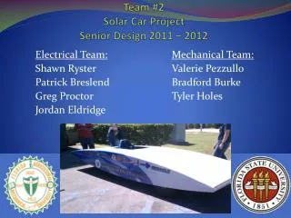
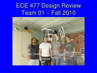
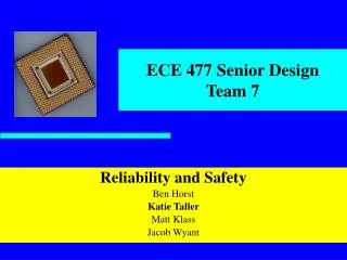
Team 01 Engineering Senior Design 2010-2011. Saturday, May 7, 2011. Outline. The Team The Project Design Norms System Overview Individual Subsystems Design Obstacles Final Design Project Assessment Acknowledgments Questions. The Team. Four electrical engineering students

E N D
Team 01Engineering Senior Design 2010-2011 Saturday, May 7, 2011
Outline • The Team • The Project • Design Norms • System Overview • Individual Subsystems • Design • Obstacles • Final Design • Project Assessment • Acknowledgments • Questions
The Team • Four electrical engineering students • Mixed software and hardware experience Amy Kendrick Nathan Avery
Project Selection • Price of energy is increasing. • Energy consumption is increasing. • Electric power metering • Provide useful data for more efficient consumption
The Project ? http://www.cpsc.gov/cpscpub/prerel/prhtml07/07036.jpg http://sp.life123.com/bm.pix/electric-meter.s600x600.jpg
The Project http://earlvillefreelibrary.org/images/computer_pic.jpg
Design Norms • Stewardship • By providing information regarding power consumption we enable consumers to make more conscious decisions about power consumption. • Transparency • The design must work as advertised and clearly alert the user to a fault. • Integrity • The design must accurately report power usage.
System Overview • E Meter • Measure all power • 3 Phase • Smart Breakers • Measure individual circuits • Circuit interruption • Base Station • Presents information
Technical Lead: Amy Ball Power Supply
Power Supply: Design • What was needed? • Alternatives • Decision
Technical Lead: Nathan Jen Smart Breakers
Smart Breakers • Provides the ‘map’ of where electricity is used • Conveniently located out of the way Pictures: http://www.home-energy-metering.com/home-energy-monitor.html http://www.thinkgeek.com/images/products/zoom/kill_a_watt.jpg
Smart Breaker: Design Decisions • Proof of concept • Use ADE7763 • NIOS II microcontroller • Solid state relay • Obstacle • Microcontroller documentation
Smart Breakers: Software • Transfer data • Check for unsafe voltage & current Arduino Uno picture: www.arduino.cc
Smart Breakers: PCB SPI Interface to Arduino Emergency Switch Metering Device Interrupter
Technical Lead: Avery Sterk Base Station
Base Station – Design Decisions • Needs to collect data from other subsystems • Best to have an always-on device • Needs to store data for future reference • Storage internal to the device • Needs to display information • Provide a familiar webpage-like interface • Best option: a single-purpose computer • Calvin already owned a suitable board
Base Station – Obstacles Obstacles Resolution LEON3 softprocessor (SPARC compatible) Bundled Linux distribution Built a custom Linux distribution from scratch Change in scope: focus on collection software • Processor selection • Operating System • Linux distribution severely disorganized and broken • Bootloader doesn’t work well with our Linux
Base Station – Final Design • Perl script to manage a ZigBee network • Use Perl and Gnuplot to chart data Camel Logo by O’Reilly Media, from www.perl.com
Techincal Lead: Kendrick Wiersma E-Meter Hardware
E-Meter Hardware: Design • MCU: MSP430 from Texas Instruments • Low power consumption • Tailored for metering applications • Integrated LCD driver • Serial Communications (RS232) • Xbee Radio • Dedicated printed circuit board
E-Meter Hardware: Obstacles Obstacles Resolution JCI etched and populated board Attach required crystals Help from Chuck Cox of SynchroSystems in Boston. Split board into two separate boards • Surface-mount components • Peripheral clocking • LCD driver • Board size limitation
E-Meter Hardware: Input Board Voltage Input Current Transformers Connection to main board
E-Meter Hardware: Main Board LCD Screen MSP430 (MCU) Connection to Input board Wireless Communication Serial (RS232) Connection
Technical Lead: Avery Sterk E-Meter Software
E-Meter Software: Design • Read current and voltage information • MSP430 reads analog information in hardware • Compute power and energy usage • Interpret data and crunch numbers • Run for a long time without resetting • Avoid overflowing data • Need to conserve power • Put features to sleep when not in use
E-Meter Software: Obstacles Obstacles Resolution Study example code and part user manuals Pre-compute conversion factors, verify results Re-configure software, make HW substitutions Create a simple interface, allow for more data sent to the base station • Interrupt-driven programming • Measurement calibration • LCD driver software was built for a different setup • Only one button for user interface
Project Assessment • Project is a success • Met our goal of measuring power • Under budget: used $360 of $700 allowance • Learning Experience • Much more than equations and schematics • Experience with new EE concepts • Troubleshooting and recovery • What we would do differently • Limit scope to improve functionality
Acknowledgements • Professor VanderLeest – team advisor • JCI: Mark Michmerhuizen, Brian Deblay, Joshua Sliter • Tim Theriault – industrial consultant • Professor Ribeiro – Engr. 315 Controls class • Bob DeKraker, Chuck Holwerda, Phil Jasperse, Glenn Remelts • Professor Medema & Bus. 396 team • SynchroSystems – Chuck Cox, John Lupien • Consumer’s Energy • Texas Instruments Thank You!
Questions ? ? ? ?