Download
1 / 53
530 likes | 656 Views
Overview of the two days. Day Two 8.30am Review and recap day one 9.00am Session I: Cable Preparation, Enclosures and Racks Connecting and patching with fibre 10.30am Morning tea 10.45am Session II: Inspection and Testing 12.00pm Lunch 12.45pm Session lll :

E N D
Overview of the two days Day Two 8.30am Review and recap day one 9.00am Session I: Cable Preparation, Enclosures and Racks Connecting and patching with fibre 10.30am Morning tea 10.45am Session II: Inspection and Testing 12.00pm Lunch 12.45pm Session lll: Fusing and splicing ribbon fibre Safe practice for fusing and splicing All participants will have access to fusion slicing equipment 2.45pm Afternoon tea 3.00pm Session IV: Ribbonizing fiber and course review Day One 8.30am Registration and coffee 8.45am Welcome and workshop overview Max Wilson and Andrew Bryson, ACFIPS 9.00am Session I: Fundamentals of fibre optics From 2500 BC to 2011 AD: The key steps. Session II: Principles of optical communication 10.15am Morning tea 10.30 am Session III: Optical fibre types and optical networks Fibre to the home and industrial networks 12.00pm Lunch 12.45pm Session IV: LAN and Telecommunications Fusion and mechanical splicing 2.45pm Afternoon tea 3.00pmSession V Factors affecting loss in ribbon fibre Measuring methods
AusOptic international • Established in 1994 • Specializing in Fiber Optics • Wide range of optical products • Regional responsibility for Fitel splicing equipment • Local Complete service of Fitel fusion splicers • Local programming of SFP/XFP • Product training on OTDR’s, Power meters, Fusion splicers • Full support for all products • Major brands, Anritsu, JDSU, Fitel, Juniper, Cisco, Ideal, Miller, Norland, Nanometer, forte.
History 1841 Daniel Colladon demonstrates light guiding in jet of water 120 years later we have lasers By 1970 we finally have fiber that have a low enough attenuation to be of use in communications • 2010 The technologies keep coming giving us better distances , more stable systems and greater capacity.
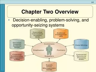
Key Components • Optical transmitters • Optical receivers • Optical fibers • Dispersion‐compensating modules • Fiber amplifiers • Optical filters, fiber Bragg gratings and couplers • Optical switches and multiplexers, reconfigurable optical add/drop multiplexers (ROADMs) • Devices for signal regeneration • Various kinds of electronics e.g. for signal processing and monitoring • Computers and software to control the system operation
from sand to a light pipe Silicon dioxide – SiO2 One of our most abundant oxide in the worlds crust As a point of interest Australia has a major producer “Simcoa Operations” in Western Australia. Silicon production commenced in December 1989. Today Simcoa is capable of producing in excess of 33,000 tonnes of high purity silicon annually.
from sand to a light pipe From is molten state glass can be produced with rapid cooling. Preforms manufactured using Vapour Deposition
from sand to a light pipe Draw towers convert the preform into the fiber before coating, preforms can make up to 30 km of fiberfrom one preform. WhenTelstra rolled out its network we had two draw towers in production. Today we only have research (small production) towers in Australia.
fiber configuration The 125um raw fiber is coated wth 250um buffer first then 900um for cord and raiser applications. In ribbon it is only coated with 250um prior to bonding or lamination
Cable Structures Four main types of Ribbon Cable Loose tube Slotted Uni Tube Patch Cord
Cable Preparation Cable preparation varies with depending on the manufacturer and the type of cable. The video from Prysmian is a resent run and give you a good idea of the accepted practice. Prysmian Cable preparation video
Connections in the Network Typical connection we have are Patch leads at both ends of the network, Fusion splicing in Universal enclosures, Field Pluggable network connections, Central office or exchange Pigtails.
Connections in the Network Starting at the Exchange, Central office or Field Access Node we have mass spliced pigtails in the racks
Connections in the Network The pigtails are presented on a ribbon fiber which enables us to splice 12 pigtails at a time. In the case of a 144 pigtails it would take about the same time as 10 single fiber pigtails.
Connections in the Network The Design of enclosure to suit Ribbon fiber has posed a few problems. Basically the fiber can not be laid up the same way as single fiber loose tube, ribbon does not have the same flexibility, as such corning took a new approach with the “spine” while others have designed new tray to accommodate the ribbon, in all cases the storage area once used to provide extra cable now accommodates fiber from the tray.
Connections in the Network Optitip and Optitap are a field ruggedized connection that is being used in FTTH While some applications need the tube fanned out in the rack, the unit shown has individual tubes for each fiber.
Fusion Splicing Splicing Technology • First Cladding Alignment Splicer by Fujikura 1977 • First LID alignment splicer by Siemens 1984 • First PAS alignment Splicer by Fujikura 1985
Fusion Splicing Michelson interference fringes give us a method to measure the shape and angle of the cleave. Polished ends are also show the effect of the glass being chipped by the blade.
Fusion Splicing Arc being vied from inside chamber plus a view of the screen
Fusion Splicing SM to BBSX splice on splicer screen and tri electrode arc
Fusion Splicing Ribbon fiber positioned in a wide even temperature zone for even splicing across all fibers.
Fusion Splicing Aligning Method: Passive
Fusion Splicing Aligning Method: Active
Fusion Splicing Types of Splicing systems • Large fiber splicing • High strength splicing • Core alignment with fiber rotation • Core alignment • Active cladding alignment • Cladding alignment
Mechanical Splice Ribbon Mechanical splices have been around for a decade, may suit emergency repairs or connections requiring a fast low set up cost solution
types of connectors Connectors, flat and radius
types of connectors MPO/MTP
types of connectors MPO/MTP ruggedized for field pluggable applications
types of connectors MPO/MTP inspection and cleaning
Loss on Optical Fiber • Rayleigh scattering - Scattering of light caused by index of refraction variations in the submicroscopic structure of the glass. • Absorption -A physical mechanism in fibers that attenuates light by converting it in to heat • Manufacturing irregularities - Such as geometric variations in core diameter or circularity, voids in the glass, defects at the core-cladding interface, and imperfect application of dopants, can cause scattering loss. However, these regularities are usually negligible in present day fibers. • Microbending - Curvatures of the fiber that involve axial displacements of a few micrometers and spatial wavelength of a few millimeters. Microbends cause loss of light and consequently increase the attenuation of the fiber. Loss due to microscopic bends in the fiber. • Macrobending - Macroscopic axial deviation of a fiber from a straight line, in contrast to microbending. Loss due to large bends in the fiber.
Loss on Optical Fiber Factors that influence the loss in a Fusion Splice
Optical Testing Power Meter
Optical Testing OTDR
Optical Testing Fiber or Traffic Identifier and VFL