Download
1 / 15
180 likes | 535 Views
GNSS Bistatic Radar. September 14, 2006 Tore Lindgren, Dennis Akos Luleå University of Technology. Introduction: - GNSS Introduction - Bistatic Radar Concept - Signal Structure - Measurement Setup Measurements: - Airplane Measurements - Tower Measurements

E N D
GNSS Bistatic Radar September 14, 2006 Tore Lindgren, Dennis Akos Luleå University of Technology
Introduction: - GNSS Introduction - Bistatic Radar Concept - Signal Structure - Measurement Setup Measurements: - Airplane Measurements - Tower Measurements Conclusions and Further Work Presentation Overview
r r r r 1 2 3 4 GPS receiver Estimating the Position of a GNSS Receiver • Satellite positions are known. • The distance is determined by time-of-arrival • Distance and position of at least 4 satellites is required to determine 3D-position and receiver clock error.
Multipath is caused by reflections that corrupt the time-of-arrival measurement. Most of the reflected signal change polarization. Multipath minimized with a good antenna. r r r r 1 2 3 4 GPS receiver Reflection Estimating the Position of a GNSS Receiver in the presence of a reflection (multipath)
The delay of the reflected signal can be used to determine the height above the ground of the receiver. The shape of the reflected signal can be used to determine properties of the ground (roughness and soil moisture). GPS receiver with zenith RHCP & nadir LHCP antennas height above ground Specular reflection GNSS Bistatic Radar Concept
GPS receiver with zenith RHCP & nadir LHCP antennas Specular reflection Reflecting object GNSS Bistatic Radar Concept • An object can cause a reflection with longer delay than the specular reflection. • Reflected GNSS signals can be used as a bistatic radar system.
Signal Structure • GPS signal buried ~18 dB under noise floor • 24 Satellites transmitting on same frequency – CDMA • Pseudo Random Noise code (PRN code), 1023 bit long • Correlate with locally generated C/A code to remove CDMA coding (i.e. make signal 1023 times stronger)
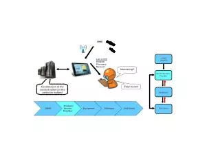
RHCP Antenna PC Direct Front End Reflect Front End Reflected Front End LHCP Antenna Measurement Setup Processing Results
Airborne (Cessna Aircraft) dynamic bistatic GPS data collection 1-July, 2005, Iowa / Des Moines, USA Lower Left is 4604808 Northing, 408000 Easting, Zone 15 (UTM) 45 40 35 30 Delta North (km) 25 20 15 10 5 0 0 10 20 30 40 50 60 Delta East (km) Airplane Measurements Aircraft speed ≈ 75 m/s Altitude ≈ 582 m Image courtesy of the USGS
Correlation Waveform for Direct and Reflected Channels Waveforms are normalized to the maximum of the direct channel
Lower Left is 4604808 Northing, 408000 Easting, Zone 15 (UTM) 40 35 30 PRN 6 25 PRN 10 Delta North (km) PRN 18 PRN 21 20 PRN 29 15 10 5 0 0 10 20 30 40 50 60 Delta East (km) Identification of Object 45 Image courtesy of the USGS
Lower Left is 4643001 Northing, 448200 Easting, Zone 15 (UTM) 3.5 3 2.5 2.55 Delta North (km) 2 2.5 1.5 2.45 Delta North (km) 2.4 1 2.35 0.5 2.3 0.4 0.45 0.5 0.55 0.6 0.65 0 0 0.5 1 1.5 2 2.5 3 3.5 Delta East (km) Delta East (km) Identification of Object Blue ellipse indicates possible sources of secondary reflections (right). This intersects with a farm (below). • More than one farm was found on ellipse • Several farms were not detected Image courtesy of the USGS
4 and 5 April, 2006, Boulder Atmospheric Observatory, Colorado, USA NordNav 300 m Tower Measurements 4 element, LHCP, antenna array RHCP patch antenna
Specular Points and Antenna Illumination • 1000 ms coherent averaging • Non-coherent averaging over 40 min
Conclusions and Further Work Use phase information of reflected signal to increase accuracy. • Secondary reflections can be used for object detection. • Advantages: • - Passive system • - Complete earth coverage • Disadvantages: • - GPS signals are weak • - Dependent on geometry and radar cross section of reflecting object