Download

1 / 34
340 likes | 464 Views
A Sustainable UK Electrical Energy Infrastructure. J.W. Spencer. Centre for Intelligent Monitoring Systems (CIMS) Dept of Electrical Engineering and Electronics. Scope of Research. Energy is a broad theme encompassing a wide range of activities,

E N D
A Sustainable UK Electrical Energy Infrastructure J.W. Spencer. Centre for Intelligent Monitoring Systems (CIMS) Dept of Electrical Engineering and Electronics
Scope of Research Energy is a broad theme encompassing a wide range of activities, including enabling and supportive technologies (e.g. control, condition monitoring etc) CIMS research addresses issues to do with: High Current phenomena. • Mainly relating to the electrical network at Transmission and Distribution levels. • Includes electric arc discharges, current interruption, alternatives to SF6. • Electrical transients in gas insulated coaxial systems etc following current interruption (i.e. high rates of rise of voltages are induced). • Electromagnetic control of high current discharges (up to 100kA).
Scope of Research Monitoring of complex conditions. • Including optical and non optical fibre sensors and systems. • Use of a generic methodology for extracting latent information from data/sensor output. • Condition monitoring. • A method for dealing with complex systems. • Cost effective monitoring.
EPSRC funded SUPERGEN V Programme(Tackling the sustainable energy infrastructure) • Part of a consortium of 6 universities (Edinburgh, Liverpool, Manchester, Queens Belfast, Strathclyde, Southampton) involved in a programme on Asset Management for Performance of Energy Systems (AMPerES). • Supported by the major transmission and distribution companies in the UK. • Liverpool is involved in 2 themes: Environmental and Monitoring. • Environmental – exploring the possible removal of Sulphur Hexafluoride from High Voltage plant. • Monitoring – cost effective monitoring of distribution and transmission substations and systems.
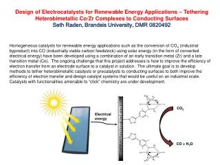
Example of High Current ResearchReplacement for SF6? • Priority theme (specifically mentioned in the Kyoto accord, National Grid, EPRI (US)) • Research work in China. • SF6 is a very good arc quenching medium due to its electronegative properties. • The chemical components at current interruption are in their dissociated state. It is these components that aid arc extinction. • Within micro-seconds the gas changes from a conductor to an insulator as the dissociate gas recombines. • Can particulates in a neutral gas (e.g. Nitrogen) provide the right chemical components to aid arc extinction and dielectric withstand?
Computer simulation with expansion chamber Finding the best arc quenching conditions e.g. gas flow, thermodynamic reactions, the right chemical species?
Expansion chamber Metallic clamping discs Polymeric powder PTFE nozzle Experimental unit
Influence of polymeric particulates on arc voltage extinction peaks from the expansion chamber.
Influence of polymeric particulates on arc voltage extinction peaks from injection.
Stills of particle / arc interaction No particles PMMA PE
112mm A A C C 18.9ms 118mm A A C C 19.8ms 125mm A A 20.7ms 20.7ms 20.7ms C Anode 50mm 68mm 130mm A A PTFE cylinder 155mm 100mm Insulated section Cathode 21.6ms 21.6ms C C Arc in air, atmospheric pressure, quasi-dc 1.5kA (7500 frames per second) 136mm A Power supply cable Supports 22.5ms C Anode (fixed contact) Interface tube PTFE ring Cathode (moving contact) PTFE cylinder containing coil HIGH SPEED PHOTOGRAPHS OF ARC CONVOLUTIONS
Insulated section 120 0 Power supply cable Supports Anode (fixed contact) Interface tube Fibre 3 PTFE ring Fibre 1 Anode Cathode (moving contact) Arc rotation Arc Fibre 2 PTFE cylinder PTFE cylinder containing coil Cathode Interrupter head Locations of the three arc monitoring, optical fibres ARC MONITORING WITH THREE OPTICAL FIBRES
Optical fibre sensors and monitoring systems • Convention was to use laser sources which are monochromatic with single mode optical fibres. • The chromatic approach uses wide band sources (e.g. white light) and multimode optical fibres. • A sensor modulates the white light and the chromaticity of the modulated signal returned to the detector is determined. • The chromatic approach provides a generic approach to optical fibre sensing and monitoring.
Take a spectrum Integrate using three non-orthogonal Gaussian functions Complex spectrum is reduced to three RGB values The RGB values are converted into three chromatic numbers H (Hue), L (Lightness) and S (Saturation)
(Spread or Bandwidth) (Dominant Wavelength) (Signal strength or Intensity)
How does Chromaticity differ from Colour? • Colour is a particular example of Chromaticity • Chromaticity is extended outside the visible spectrum • Responsivities of detectors and processors are variable • Defines information in terms of a limited number of cross correlated signals • Chromatic methods may be deployed not only using wavelength but also time, frequency, space, mass, acoustic etc domains • Chromatic processing can extend to more than 3 spectral parameters, generally up to 6. • It is a highly flexible approach and uses readily available detectors and sources but used in unconventional manners
Amp. Response Time t3 t2 Freq. t1 Chromatic process Intensity Dominant freq. Bandwidth R G B Chromatic processing
Opto - Acoustic monitoring of a tap changing transformer at a distribution substation
Location of first tap change 5 -> 4 Sample signal from tap changing transformerwith tap change.
Transformer oil monitoring Light source and detection units Optical spectrum analyser Sample of oil
Chromatic values for oil samples Oil of concern Oil not of concern Fresh oil empty cuvette
Technology Transfer Ongoing • Fuel quality (KTP) • Detection of Bacterial Growth (KTP) • Optical fibre based temperature sensors for HV transformer winding monitoring (KTP) Future possible • Oil monitoring (Joule Centre) • Opto-acoustic monitoring system (required ~ 37 units required for 2 DNOs) (Manufacturer and end user supported University’s KT bid).
Conclusions • There are direct technologies that lead to obvious savings in CO2 and CO2e emissions. • Enabling and supportive technologies are important and can assist in reducing CO2 and CO2e emissions.