Download
1 / 33
330 likes | 468 Views
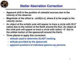
Yu. Senichev Electrostatic lattice with alternating spin aberration. “Tomas-Bargmann, Michel,Telegdi” equation with EDM term. The spin is a quantum value , but in the classical physics representation the “spin” means an expectation value of a quantum mechanical spin operator:. EDM.

E N D
Yu. SenichevElectrostatic lattice with alternatingspin aberration
“Tomas-Bargmann, Michel,Telegdi” equation with EDM term • The spin is a quantum value, but in the classical physics representation the “spin” means an expectation value of a quantum mechanical spin operator: EDM
Main problems of EDM simulation • the arithmetic coprocessor has a mantissa length of 52 bits (minimum recorded figure~2*10-16) and can make a mistake in calculating spin projections after i-th element if Si+1-Si<10-16. • the required revolution time simulation is ~109 • high accuracy of simulation Therefore we take an approach, where the EDM signal is not implemented, and only the induced error signal is studied.
Methods of spin-orbital motion investigation • -COSY Infinity program; • -Symplectic Runge-Kutta integrating program; • -Direct numerical integration of T-BMT differential equations by Fortran subroutine; • -Analytical approach.
COSY Infinity program (M. Berz, MSU) • COSY Infinity is a program for the simulation, analysis and design of particle optical systems, based on differential algebraic methods. • In the EDM search, it is the only program which allows the spin-orbit motion of millions of particles to be simulated over a real time scale experiment during n x1000 seconds. • At present, we use the MPI (Message Passing Interface) version of the COSY Infinity program installed on a supercomputer with 3·105 processors. • At the initial stage of EDM research, we use COSY Infinity to study the behaviour of the spin aberrations for a large number of particles and a long-time calculation.
Symplectic Runge-Kutta integrating (A. Ivanov, St.PbSU) • The integrating Runge-Kutta program is intended to model the spin-orbital motion with fringe fields in elements and including the EDM signal directly in the simulation. • The algorithm used in the program is not as fast as COSY Infinity by several orders of magnitude. Therefore, we use it mostly to investigate a short-time phenomenon for single particle that does not require long calculation periods. • As a basic method for the tracking program, a symplectic Runge-Kutta scheme was implemented from W. Oevel, M. Sofroniou, • ( Symplectic Runge- Kutta Schemes II: Classification of Symmetric Methods, preprint, University of Paderborn, Germany, 1996.)
The EDM search methods in Storage Ring: • Resonant method with initial spin orientation in ring • S║B; S={0,Sy ,0} and B={0,By,0} • 2. “Magic” method with initial spin orientation in ring • S║p;S┴E; S={0,0,Sz} and E={Ex,0,0} • in three electrostatic lattices based on: • electrostatic deflectors with optimized 2D-profile with quadrupoles and without sextupoles; • electrostatic deflectors with quadrupoles and optimized sextupoles; • electrostatic continuous deflector with optimized 2D-profile (YkS) without quadrupoles and without sextupoles.
In resonant method* the spin frequency is parameterized : • using RF flipper . • In case of parametric resonance when we shall observe the resonant build up: • Advantage: the method can be • realized in COSY ring • Disadvantage: the high requirement • to stability of frf *A.Lehrach, B.Lorentz, W.Morse, N.Nikolaev and F.Rathmann
“Magic” method for purely electrostatic ring • In the “magic” method the beam is injected in the electrostatic ring with the spin directed along momentum S║p and S┴E; S={0,0,Sz} and E={Ex,0,0} • at “magic” energy : External fields EDM
“Magic” method in purely electrostatic ring • In purely electrostatic ring the spin of particle with “magic energy” rotates with the same angular frequency as the momentum and it tilts up in the YZ plane due to the EDM with angular rate
Spin tune aberration in purely electrostatic ring • In reality the beam has energy spread γmag±Δγ and all particles move in different external field. Therefore the spin tune has the aberrations dependent on energy γ and trajectory r(t) of particles. • At “magic” energy it is no precession of spin. For no “magic” energy γmag±Δγ vs energy vs field distribution Spin tune aberration
Spin Coherence Time is time when RMS spin orientation of the bunch particles reaches one radian (YS,BNL), and it has to be > 1000sec. • During SCT each particle performs ~109 turns in the storage ring moving with different trajectories through the optics elements. • At such conditions the spin-rotation aberrations associated with various types of space and the time dependent nonlinearities start to play a crucial role.
Spin tune aberration due to energy spread • Longitudinal component
RF cavity as first step to increase SCT • RF off: • for Δp/p=10-4SCT=6300 turns, which is ~ 1 msec. • RF on: • Idea of using the RF cavity was expressed long time ago by many authors, for instance [ A.P. Lysenko et al., Part.Accel. 18, 215 (1986)]. • The spin swing in a rapidly oscillating field with RF frequency and it is bounded within a very narrow angle ~10-6 dependent on
RF on: Second order approach of spin tune versus Δp/p • However, in the second approach versus momentum the average tune spin is not zero • At (Δp/p)max=10-4 and an axial • particle the number of turns for • SCT is ~6 107 turns, that is ~180 sec. • The code COSY infinity simulation
Off-axial particle: Longitudinal-transverse coupling in electrostatic storage ring • The electrical deflector has the central field symmetry: • where angular momentum . • Due to this fact the total energy can be represented as the function of the coordinates : • The radial motion is one dimensional motion in the field with the effective potential, and the equilibrium radius:
Off-axial particle: influence on spin motion • The particle with different momentum oscillates with respect to different energy levels: • COSY infinity tracking results • for initial coordinates x=0, y=0 and x=3mm, y=0. • Thus, RF cavity will not be able to reduce the oscillation of the spin for off-axial particles, since:
Equilibrium energy level modulation as method to increase SCT • Following physical logic the only solution to increase SCT is the modulation of the energy level itself relative of the magic level. • For this purpose, we have increase coupling between longitudinal and transverse motion that is, approach frequencies as close as possible to each other. In result we have got SCT=400 sec • COSY infinity tracking results • for initial coordinates x=0, y=0 and x=3mm, y=0.
Spin tune aberration vs momentum and axial deviation • Assuming violation “magic” condition for non-reference particle the spin tune aberration is defined: • with
Spin tune aberration vs momentum • Grouping the coefficients of powers up to second order, we obtain an equation having a parabolic form: • with coefficients having a parabolic dependence on axial deviation
Spin tune aberration vs axial deviation • Grouping the coefficients of powers up to second order, we obtain an equation having a parabolic form: • with coefficients having a parabolic dependence on momentum
Spin tune aberration vs and • Convex surface, or concave surface depends on the sign of +
Two steps to minimize the spin aberrations • The lattice with a compensation of the mutual influence of deflector parameters and lattice parameters • The lattice must provide the alternate change of the spin aberration surface from concave to convex and vice versa
First step • We first investigate the structure with deflector having a purely cylindrical electrodes: • Figure: Maximum spin deflection angle after billion turns versus k2
Method realization • Question is how to customize the required k1 , k2 ?
Second step: alternating spin aberration method • The ring is equipped with two types of deflector with • and • changing from one deflector to another. • In such optics is easier to achieve minimum spin aberration • Raising the field strength between the plates in even deflectors • and reducing in the odd deflectors it effectively adjusts the • required coefficients k1 and k2. It allows to adjust the spin of • aberration to minimum.
Alternating spin aberration method • Another possibility is the creation of the required potential distribution due to potential changes in stripline deposited on the surface of the ceramic plates. • Such plates may be the additional corrective elements placed on the sides of the main deflector
First step • The maximum flatness of spin aberration surface is reached in the alternating spin aberration lattice • Figure: Maximum spin deflection angle after billion turns versus x deviation
Electrostatic lattice consisting of electrostatic deflectors and electrostatic quadrupoles • Figure: Twiss functions of electrostatic ring for ring and one cell
Comparison with other lattices • Alternating spin aberration
The limit capabilities of alternating spin aberration method • The spread due to final Δp/p it is impossible to remove completely using the correct k1 and k2 only. Nevertheless the total spread of spin deflection angle does not exceed ±0.5 rad after billion turns, which one corresponds to a SCT about 5000 seconds.
Tracking results: • We used differential algebra methods realized in COSY Infinity and integrating program with symplectic Runge-Kutta methods. • 1. Cylindrical deflector: after 106 turns Sxrms≈0.002 that is SCT~500 sec • 2. Alternating k2 deflector: after 106 turns Sxrms≈0.0002 that is SCT~5000 sec
Conclusion: • -we have studied the behavior of spin aberration in the structure and developed techniques to minimize it; • -one of the most effective methods is the alternating spin aberration; • -the analytical model allows finding the general solution of the retention of aberrations within the values allowed SCT to have about 5000 seconds confirmed by COSY-Infinity.