Download
1 / 139
1.42k likes | 1.61k Views
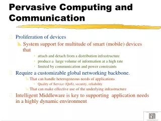
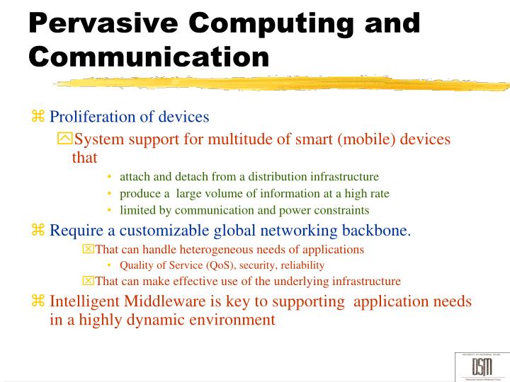
Pervasive Computing and Communication. Proliferation of devices System support for multitude of smart (mobile) devices that attach and detach from a distribution infrastructure produce a large volume of information at a high rate limited by communication and power constraints

E N D
Pervasive Computing and Communication • Proliferation of devices • System support for multitude of smart (mobile) devices that • attach and detach from a distribution infrastructure • produce a large volume of information at a high rate • limited by communication and power constraints • Require a customizable global networking backbone. • That can handle heterogeneous needs of applications • Quality of Service (QoS), security, reliability • That can make effective use of the underlying infrastructure • Intelligent Middleware is key to supporting application needs in a highly dynamic environment
In the last 5 years….. • New devices w/ new capabilities • Data capture, storage, presentation • New apps • Social networking,…. • Multimedia applications, gaming, data capturing, download/upload/streaming • Information seek/notification • New network infrastructures • DTN, WiMax, UWB,… • New computational infrastructure • Cloud computing, grids… New problems and challenges…
Laptop Users Applications BS Mobile Devices Networks GSM or CDMA ad hoc network PDA WLAN Access Point Cell Phone Introduction Mobile Ecosystem
Technology Incentive • Growth in computational capacity • MM workstations with audio/video processing capability • Dramatic increase in CPU processing power • Dedicated compression engines for audio, video etc. • Rise in storage capacity • Large capacity disks (several gigabytes) • Increase in storage bandwidth,e.g. disk array technology • Surge in available network bandwidth • high speed fiber optic networks - gigabit networks • fast packet switching technology
CS234 – Mobile Computing Tuesdays, Thursdays 3:30-4:50p.m. ICS 243 Prof. Nalini Venkatasubramanian nalini@ics.uci.edu
Outline • The Future: Mobile and Pervasive Computing • An Applications View • A Content View • Multimedia Content • QoS Basics and End-to-end support • A Systems View • Device, Operating System • Networks, Middleware • Application, Content • A Cross-Layer Approach to Systems Support • Supporting Cross Cutting Concerns (Security, Reliability, Heterogeneous Interoperability)
Enabler: Mobile Communication Networks • Cellular - GSM (Europe+), TDMA & CDMA (US) • FM: 1.2-9.6 Kbps; Digital: 9.6-14.4 Kbps (ISDN-like services) • Public Packet Radio - Proprietary • 19.2 Kbps (raw), 9.6 Kbps (effective) • Private and Share Mobile Radio • Wireless LAN - wireless LAN bridge (IEEE 802.11) • Radio or Infrared frequencies: 1.2 Kbps-15 Mbps • Paging Networks – typically one-way communication • low receiving power consumption • Satellites – wide-area coverage (GEOS, MEOS, LEOS) • LEOS: 2.4 Kbps (uplink), 4.8Kbps (downlink)
Device Characteristics • Battery Power restrictions • Transmit/receive, disk spinning, display, CPUs, memory consume power • Resource constraints • Mobile computers are resource poor • Reduce program size • Computation and communication load cannot be distributed equally • Small screen sizes
Wireless network characteristics • Variant Connectivity • Low bandwidth and reliability • Frequent disconnections • predictable or sudden • Asymmetric Communication • Broadcast medium • Monetarily expensive • Charges per connection or per message/packet • Connectivity is weak, intermittent and expensive
Mobility Characteristics • Location changes • location management - cost to locate is added to communication • Heterogeneity in services • bandwidth restrictions and variability • Dynamic replication of data • data and services follow users • Querying data - location-based responses • Security and authentication • System configuration is no longer static
Challenges • Application Context • Increasing QoS., security, reliability demands • Soft Real Time Constraints • Support for traditional media (text, images) and continuous media (audio/video) • Synchronization (e.g. lip sync., floor control) • System support for multitude of components • Attach and detach from a distributed infrastructure • Deal with large vol. of information at a high rate • Changing global system state Application Context Global Context Challenges Device Context Network Context • Need high degree of “network awareness” and “customizability” • congestion rates, mobility patterns etc. • QoS driven resource provisioning • Heterogeneous networks • Heterogeneous devices • Limited battery lifetime • Size/weight limitations • Computation/Communication constraints
Cellular Networks Includes slides by Prof. Lichun Bao and others
Principles of Cellular Networks • Underlying technology for mobile phones, personal communication systems, wireless networking etc. • Developed for mobile radio telephone • Replace high power transmitter/receiver systems • Typical support for 25 channels over 80km • Use lower power, shorter range, more transmitters
Cellular Network Organization • Multiple low power transmitters • 100w or less • Area divided into cells • Each with own antenna • Each with own range of frequencies • Served by base station • Transmitter, receiver, control unit • Adjacent cells on different frequencies to avoid crosstalk
Shape of Cells • Square • Width d cell has four neighbors at distance d and four at distance d • Better if all adjacent antennas equidistant • Simplifies choosing and switching to new antenna • Hexagon • Provides equidistant antennas • Radius defined as radius of circum-circle • Distance from center to vertex equals length of side • Distance between centers of cells radius R is R • Not always precise hexagons • Topographical limitations • Local signal propagation conditions • Location of antennas
Frequency Reuse • Power of base transceiver controlled • Allow communications within cell on given frequency • Limit escaping power to adjacent cells • Allow re-use of frequencies in nearby cells • Use same frequency for multiple conversations • 10 – 50 frequencies per cell • E.g. • N cells all using same number of frequencies • K total number of frequencies used in systems • Each cell has K/N frequencies • Advanced Mobile Phone Service (AMPS) K=395, N=7 giving 57 frequencies per cell on average
FrequencyReusePatterns • N = number of cells in repetitious pattern, i.e. Reuse factor • Each cell in pattern uses unique band of frequencies
Increasing Capacity (1) • Add new channels • Not all channels used to start with • Frequency borrowing • Taken from adjacent cells by congested cells • Or assign frequencies dynamically • Cell splitting • Non-uniform distribution of topography and traffic • Smaller cells in high use areas • Original cells 6.5 – 13 km • 1.5 km limit in general • More frequent handoff • More base stations
Increasing Capacity (2) • Cell Sectoring • Cell divided into wedge shaped sectors • 3 – 6 sectors per cell • Each with own channel set • Subsets of cell’s channels • Directional antennas • Microcells • Move antennas from tops of hills and large buildings to tops of small buildings and sides of large buildings • Even lamp posts • Form microcells • Reduced power • Good for city streets, along roads and inside large buildings
Operation of Cellular Systems • Base station (BS) at center of each cell • Antenna, controller, transceivers • Controller handles call process • Number of mobile units may in use at a time • BS connected to mobile telecommunications switching office (MTSO) • One MTSO serves multiple BS • MTSO to BS link by wire or wireless • MTSO: • Connects calls between mobile units and from mobile to fixed telecommunications network • Assigns voice channel • Performs handoffs • Monitors calls (billing) • Fully automated
Channels • Control channels • Setting up and maintaining calls • Establish relationship between mobile unit and nearest BS • Traffic channels • Carry voice and data
Typical Call in Single MTSO Area (1) • Mobile unit initialization • Scan and select strongest set up control channel • Automatically selected BS antenna of cell • Usually but not always nearest (propagation anomalies) • Handshake to identify user and register location • Scan repeated to allow for movement • Change of cell • Mobile unit monitors for pages (see below) • Mobile originated call • Check set up channel is free • Monitor forward channel (from BS) and wait for idle • Send number on pre-selected channel • Paging • MTSO attempts to connect to mobile unit • Paging message sent to BSs depending on called mobile number • Paging signal transmitted on set up channel
Typical Call in Single MTSO Area (2) • Call accepted • Mobile unit recognizes number on set up channel • Responds to BS which sends response to MTSO • MTSO sets up circuit between calling and called BSs • MTSO selects available traffic channel within cells and notifies BSs • BSs notify mobile unit of channel • Ongoing call • Voice/data exchanged through respective BSs and MTSO • Handoff • Mobile unit moves out of range of cell into range of another cell • Traffic channel changes to one assigned to new BS • Without interruption of service to user
Other Functions • Call blocking • During mobile-initiated call stage, if all traffic channels busy, mobile tries again • After number of fails, busy tone returned • Call termination • User hangs up • MTSO informed • Traffic channels at two BSs released • Call drop • BS cannot maintain required signal strength • Traffic channel dropped and MTSO informed • Calls to/from fixed and remote mobile subscriber • MTSO connects to PSTN • MTSO can connect mobile user and fixed subscriber via PSTN • MTSO can connect to remote MTSO via PSTN or via dedicated lines • Can connect mobile user in its area and remote mobile user
Mobile Radio Propagation Effects • Signal strength • Strength of signal between BS and mobile unit strong enough to maintain signal quality at the receiver • Not strong enough to create too much cochannel interference • Noise varies • Automobile ignition noise greater in city than in suburbs • Other signal sources vary • Signal strength varies as function of distance from BS • Signal strength varies dynamically as mobile unit moves • Fading • Even if signal strength in effective range, signal propagation effects may disrupt the signal
Mobile Internet Mobile IP (MIP) Introduction (goals, architecture, protocol, examples) MIP messages, encapsulations MIP issues: triangular routing, reverse tunneling, MobileIPv6 Micro-mobility Protocols Cellular IP HMIP MobileNAT Summary Mobile Ad Hoc Networks Introduction: difference from Wireless Sensor Networks (WSNs) Routing Protocols WRP AODV DSR Improvements: interference levels topology control/management Summary Networks for Mobile Computing Wireless Networking
Motivation for Mobile IP • Internet routing • based on IP destination address and network prefix • change of physical subnet implies that the mobile node should • change its IP address to have a topologically correct address • Challenges – 1) find the MS, 2) avoid disconnection • DNS? Updates take to long time • Per-host routing? Too many entries in the RT. • Solution: • Mobile IP is an open standard, defined by the Internet Engineering Task Force (IETF) RFC 2002, that allows users to keep the same IP address, stay connected, and maintain ongoing applications while roaming between IP networks • Network supported Mobile IP (tunneling in IPv4) • Host supported Mobile IPv6 (Routing extension header) Wireless Networking
Requirements to Mobile IP (RFC 3344) • Transparency • Mobile keeps its IP address when changing subnets • Communication continues after interruption of link possible • Compatibility • no changes to current end-systems and routers required - tunneling • no changes to fixed systems – HA-FA tunneling • Security • authentication of all registration messages – MIP messages • Efficiency and scalability • only a few additional messages to the mobile system required (connection typically via a low bandwidth radio link) – MIP messaging • Global support of a large number of mobile systems in the whole Internet – HA for MN Wireless Networking
Architectural Components • End system elements • Mobile Node (MN) • Correspondent Node (CN): communication partner • Network elements • Home Agent (HA): System in the home network of the MN, typically a router • Registers the location of the MN, tunnels IP datagrams to the COA • Foreign Agent (FA): the default router for MN • Forwards the tunneled datagrams to the MN • Can be collocated with MN • Care-of Address (COA): address of the current tunnel end-point for the MN • Can be associated with the MN or FA. Wireless Networking
Mobile IP Protocol • Agent Advertisement using ICMP • HA and FA periodically send advertisement messages into their physical subnets in ICMP messages • MN listens to these messages and detects, if it is in the home or a foreign network (standard case for home network) • MN reads a COA from the FA advertisement messages • MN may send out router (agent) solicitation. • Registering the COA using UDP • binding for the mobile node – tuple (home address, COA, registration lifetime, authentication) • binding update sent by MN to HA for remote redirect. • Traffic forwarding using Tunneling • HA advertises the IP address of the MN (as for fixed systems) via proxy ARP • routers adjust their entries, these are stable for a longer time (HA responsible for a MN over a longer period of time) • packets to the MN are sent to the HA, which tunnels to the COA. • independent of changes in COA/FA Wireless Networking
Example network HA MN Internet router home network mobile end-system (physical home network for the MN) FA foreign network router (current physical network for the MN) CN end-system router Wireless Networking
Data transfer to the mobile system HA 2 MN Internet home network 3 receiver foreign network FA 1. Sender sends to the IP address of MN, HA intercepts packet (via proxy ARP) 2. HA tunnels packet to COA, here FA, by encapsulation 3. FA forwards the packet to the MN 1 CN sender Wireless Networking
Data transfer from the mobile system HA 1 MN Internet home network sender FA foreignnetwork 1. Sender sends to the IP address of the receiver as usual, FA works as default router CN receiver Wireless Networking
Design Factors • Propagation effects • Dynamic • Hard to predict • Maximum transmit power level at BS and mobile units • Typical height of mobile unit antenna • Available height of the BS antenna • These factors determine size of individual cell • Model based on empirical data • Apply model to given environment to develop guidelines for cell size • E.g. model by Okumura et al refined by Hata • Detailed analysis of Tokyo area • Produced path loss information for an urban environment • Hata's model is an empirical formulation • Takes into account variety of environments and conditions
WLAN technologies Adapted from slides by Prof. Lichun Bao and others
54 Mbps 802.11{a,g} 5-11 Mbps .11 p-to-p link 802.11b 1 Mbps 802.15 3G 384 Kbps UMTS/WCDMA, CDMA2000 2G 56 Kbps IS-95 CDMA, GSM Outdoor 50 – 200m Mid range outdoor 200m – 4Km Long range outdoor 5Km – 20Km Indoor 10 – 30m Characteristics of selected wireless standards Wireless Networking
network infrastructure Elements of a wireless network • Wireless stations • APs, laptops, PDAs, IP phones - run applications • may be stationary (non-mobile) or mobile • Wireless links • typically used to connect mobile to base station, also used as backbone link • multiple access protocol coordinates link access • various data rates, transmission distance Wireless Networking
network infrastructure Operational modes of a wireless network – Infrastructure mode • base station • typically connected to wired network • responsible for sending packets between wired network and wireless host(s) in its “area”. e.g., cell towers 802.11 access points • Handoff: mobile changes base station providing connection into wired network Wireless Networking
Operational modes of a wireless network – Infrastructure mode Ad hoc mode • no base stations • nodes can only transmit to other nodes within link coverage • nodes organize themselves into a network: route among themselves Wireless Networking
Evaluations of Wireless LANs • Advantages • Flexible deployments (infrastructure and ad hoc modes) • Robust against disasters like, e.g., earthquakes, fire • Disadvantages • typically lower bandwidth compared to wired networks (1-10 Mbit/s) • many proprietary solutions, products have to follow many national restrictions, it takes a vary long time to establish global solutions, e.g., IMT-2000 Wireless Networking
Design Goals for Wireless LANs • Design • Data plane: • Channel efficiency: robust transmission technology • Power efficiency: low power for battery use • Management plane: • easy to use for everyone, easy to program • security (authentication, authorization, accounting and privacy), safety (low radiation) • Operation • global, seamless operation – protection of investments in wired networks • no special permissions or licenses needed to use the LAN • Infrastructure-mode and ad-hoc-mode support • transparency concerning applications and higher layer protocols, but also location awareness if necessary Wireless Networking