Download
1 / 10
100 likes | 240 Views
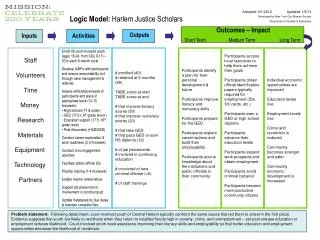
EE Support TEV Abort Inputs. HOPS (QFA4, QFE1, QFF3, QDD1, QDE2, QDF4, SF, SD, &SQ) Abort = Power Supply OFF DIPOLE CORRECTORS (275 PSs located around ring) Abort = Power Supply OFF C0 SHUNT (T:C0SH) Abort = +/- 0.5 amp or greater regulation error 100 amps maximum

E N D
EE Support TEV Abort Inputs • HOPS(QFA4, QFE1, QFF3, QDD1, QDE2, QDF4, SF, SD, &SQ) Abort = Power Supply OFF • DIPOLE CORRECTORS(275 PSs located around ring) Abort = Power Supply OFF • C0 SHUNT (T:C0SH) Abort = +/- 0.5 amp or greater regulation error 100 amps maximum 11 amps/sec max. slew rate
EE Support TEV Abort Inputs(Cont.) • LOW BETA QUADS 1 kamp PSs (AQ7, AQ9, AQ0, BQ7, BQ9, BQ0, CQ9, CQ0, DQ7, DQ9, & DQ0) Abort = Power Supply OFF High Current PSs (B0Q1, B0Q2-4, B0Q3, B0Q5, B0Q6, D0Q1, D0Q2-4, D0Q3, D0Q5, D0Q6) Abort = +/- 15 amps or greater regulation error and/or, PS OFF • F17 Kicker Abort = Tripped/OFF
EE Support TEV Abort Inputs(Cont.) • TECAR (1, VME-based uP in A2) TEV Ramp generation and PS Voltage profiles QPM Communications See System logic diagram for ABORT detailed actions Abort Summary: QPM link failures Overcurrent PS Loop
EE Support TEV Abort Inputs(Cont.) • QPMs(24, Power PC uPs, one in every 1-4 building) TEV Magnet Quench Protection Monitors See System logic diagram for detailed abort actions Abort Summary: TEV Main PSs QUENCHes LEAD Failures Quench Protection System Faults (Dumps, HFUs, QBSs, UPSs) Timing: 3 ms filtering in VFCs 60 Hz sampling of UP/DWN counters 3, line cycle averaging 0.5 volt detection level
TEV Quench Protection Voltage Meas. Magnet ½ Cell