Download
1 / 63
670 likes | 875 Views
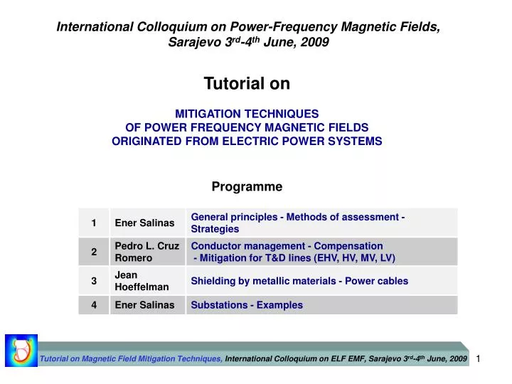
Tutorial on Magnetic Field Mitigation Techniques, International Colloquium on ELF EMF, Sarajevo 3 rd -4 th June, 2009. International Colloquium on Power-Frequency Magnetic Fields, Sarajevo 3 rd -4 th June, 2009. Tutorial on MITIGATION TECHNIQUES OF POWER FREQUENCY MAGNETIC FIELDS

E N D
Tutorial on Magnetic Field Mitigation Techniques, International Colloquium on ELF EMF, Sarajevo 3rd-4th June, 2009 International Colloquium on Power-Frequency Magnetic Fields, Sarajevo 3rd-4th June, 2009 Tutorial on MITIGATION TECHNIQUES OF POWER FREQUENCY MAGNETIC FIELDS ORIGINATED FROM ELECTRIC POWER SYSTEMS Programme
Tutorial on Magnetic Field Mitigation Techniques, International Colloquium on ELF EMF, Sarajevo 3rd-4th June, 2009 About the working group C4.204 • CIGRÉ Working Group formed in 2001 • Motivation: Concerns from customers, utilities and researchers in relation to some alleged health risks (in particular childhood leukaemia) of long-term exposure to power frequency magnetic fields • Initial aim: To collect discuss and synthesise the available technical data referring to different existing techniques to mitigate extremely low frequency (ELF) magnetic fields • Final form: A published Technical Brochure (TB 373)
Tutorial on Magnetic Field Mitigation Techniques, International Colloquium on ELF EMF, Sarajevo 3rd-4th June, 2009 1.1 General Principles
Tutorial on Magnetic Field Mitigation Techniques, International Colloquium on ELF EMF, Sarajevo 3rd-4th June, 2009 Sources of power-frequency magnetic fields (PFMFs) • The flow of electrical energy from the generation plant to the customer. • Along the way there are different types of sources of power-frequency magnetic fields • The PFMFs sources and techniques can be classified according to their origin: • Power lines • Underground cables • Complex sources (e.g. substations)
ELECTRIC FIELD MAGNETIC FIELD Effect on humans Tutorial on Magnetic Field Mitigation Techniques, International Colloquium on ELF EMF, Sarajevo 3rd-4th June, 2009 Difference between Electric and Magnetic fields • The magnetic field B penetrates the house easily • Only certain materials with specific geometries or dedicated circuits could oppose to this action • The purpose of designing mitigation techniques is to find out what are the most appropriate materials, geometries or circuits that achieve this action effectively • The electric field E does not penetrate the house • As the field reaches the walls, the electric charges (generated as a consequence of this field) are diverted to earth and recombined • Even in the case of lightning, the lightning rods connected to ground will do this diversion successfully
“Deviation” “Rejection” Magnetic fields can have different interactions with different materials Some important design parameters: Shielding Factor Skin depth Tutorial on Magnetic Field Mitigation Techniques, International Colloquium on ELF EMF, Sarajevo 3rd-4th June, 2009 (c) (d) AC Source Ferromagnetic enclosure (a) (b) Region of interest Region of interest Region of interest Coil Ferromagnetic Plate Pure conductive Plate Region of interest Interaction of AC magnetic fields with materials “Concentration” The geometry and the field incidence are also important!
Biot-Savart formula Tutorial on Magnetic Field Mitigation Techniques, International Colloquium on ELF EMF, Sarajevo 3rd-4th June, 2009 1.2 Methods of assessment of the mitigation techniques Analytical Numerical At power frequency we use the quasi-static approximation, i.e. displacement currents are neglected Shielding experiments with busbars and conductors at normal scale Experimental Small scaleexperiment of a 3-phase underground cable
Tutorial on Magnetic Field Mitigation Techniques, International Colloquium on ELF EMF, Sarajevo 3rd-4th June, 2009 1.3 Some strategies for mitigation A relevant factor regarding the technique to use is the choice of the location i.e. where it is to be applied. In other words apply it to the source or to the area of interest? As a general rule, it may seem natural to think that it will be more cost-effective to mitigate at the source than at the area of interest. However, the choice can be different. For example in some cases where the source is rather large (e.g. long busbars); or if the purpose is to mitigate the field in a small region. This is not an easy question since the definition of the area of interest is not always unambiguous. The green outlines are symbolic representations – not necessarily metal plates – they could indicate a loop, an active device, or any other mitigation action within that region.
Tutorial on Magnetic Field Mitigation Techniques, International Colloquium on ELF EMF, Sarajevo 3rd-4th June, 2009 International Colloquium on Power-Frequency Magnetic Fields, Sarajevo 3rd-4th June, 2009 Tutorial on MITIGATION TECHNIQUES OF POWER FREQUENCY MAGNETIC FIELDS ORIGINATED FROM ELECTRIC POWER SYSTEMS Programme 9
2.1 Conductor management Applied mostly to linear sources: overhead lines, underground cables, busbars, etc. Balanced system !! Tutorial on Magnetic Field Mitigation Techniques, International Colloquium on ELF EMF, Sarajevo 3rd-4th June, 2009 Original configuration Compaction Layout Change of geometry of conductors keeping the same phase-to-phase clearance Keeping the same geometry reduce the phase-to-phase clearance Contour curves values in T 10
2.1 Conductor management Faster reduction with distance to source !! Tutorial on Magnetic Field Mitigation Techniques, International Colloquium on ELF EMF, Sarajevo 3rd-4th June, 2009 Phase splitting Single-phase line Current dipole Current quadrupole r : Distance to centre of quadrupole r : Distance to centre of dipole 11
2.1 Conductor management Tutorial on Magnetic Field Mitigation Techniques, International Colloquium on ELF EMF, Sarajevo 3rd-4th June, 2009 Phase splitting Three-phase line Two split phases Three split phases No great improvement !! 12
2.1 Conductor management Tutorial on Magnetic Field Mitigation Techniques, International Colloquium on ELF EMF, Sarajevo 3rd-4th June, 2009 Phase cancelation Multi-circuit line Super bundle Low-reactance Both circuits should be equally loaded Changes in protection relays could be needed Changes in corona performance in overhead circuits 13
2.2 Compensation Tutorial on Magnetic Field Mitigation Techniques, International Colloquium on ELF EMF, Sarajevo 3rd-4th June, 2009 Passive compensation Location close to the source of a loop or coil. Magnetic field generated by the coil that partially compensates the original field. Induced current in the loop due to the flux linkage. Increase of effectiveness: insertion of capacitor to compensate the inductance of the loop. • Design parameters: • Shape of the coil • Location of the coil • Electrical parameters of the conductor • Number of coils Not complete compensation !! 14
2.2 Compensation Tutorial on Magnetic Field Mitigation Techniques, International Colloquium on ELF EMF, Sarajevo 3rd-4th June, 2009 Passive compensation Single-phase line Loop With capacitor Contour curves values in T 15
2.2 Compensation Tutorial on Magnetic Field Mitigation Techniques, International Colloquium on ELF EMF, Sarajevo 3rd-4th June, 2009 Active compensation Current in the loop generated by an external power source. Current control in amplitude and phase. More sophisticated equipment is required. Costly and less reliable than the passive loop. Higher flexibility in the location of the loop. Possibility of locating it far from the source. Not complete compensation !! 16
2.3 Mitigation for T&D overhead lines Tutorial on Magnetic Field Mitigation Techniques, International Colloquium on ELF EMF, Sarajevo 3rd-4th June, 2009 Techniques Increasing the height of masts Conductor management Compensation • Medium-high cost • Medium-high reduction factor • Low-medium cost • Low-medium reduction factor • Medium-high cost • Low-medium-high reduction factor Shielding factor = reduction factor !! 17
2.3 Mitigation for T&D overhead lines Tutorial on Magnetic Field Mitigation Techniques, International Colloquium on ELF EMF, Sarajevo 3rd-4th June, 2009 EHV and HV Power lines Increasing the height of masts Reduction restricted to underneath the line. Reduction factor at x=0 18
2.3 Mitigation for T&D overhead lines Tutorial on Magnetic Field Mitigation Techniques, International Colloquium on ELF EMF, Sarajevo 3rd-4th June, 2009 EHV and HV Power lines Conductor management: changing the geometry of conductors 380 kV Low reduction factor close to the line Low reduction factor far from the line 19
2.3 Mitigation for T&D overhead lines Tutorial on Magnetic Field Mitigation Techniques, International Colloquium on ELF EMF, Sarajevo 3rd-4th June, 2009 EHV and HV Power lines Conductor management: compaction Medium reduction factor 115 kV • Lower visual impact • Reduction of line surge impedance • Difficult to perform live-line maintenance • EHV line: increase of corona effect 20
2.3 Mitigation for T&D overhead lines Tutorial on Magnetic Field Mitigation Techniques, International Colloquium on ELF EMF, Sarajevo 3rd-4th June, 2009 EHV and HV Power lines Conductor management: phase cancellation 380 kV 1500 A Low reduction factor close to the line Medium reduction factor far from the line 21
2.3 Mitigation for T&D overhead lines Tutorial on Magnetic Field Mitigation Techniques, International Colloquium on ELF EMF, Sarajevo 3rd-4th June, 2009 EHV and HV Power lines Conductor management: phase splitting 380 kV 1500 A Medium reduction factor close to the line High reduction factor far from the line Star line: complete reduction at 35 m !! 22
2.3 Mitigation for T&D overhead lines Tutorial on Magnetic Field Mitigation Techniques, International Colloquium on ELF EMF, Sarajevo 3rd-4th June, 2009 EHV and HV Power lines Passive compensation Low reduction factor close to the line Medium reduction factor far from the line at one side High reduction factor far from the line at the other side Capacitor: non-symmetrical reduction!! 23
2.3 Mitigation for T&D overhead lines Tutorial on Magnetic Field Mitigation Techniques, International Colloquium on ELF EMF, Sarajevo 3rd-4th June, 2009 EHV and HV Power lines Effect on other electrical parameters 24
Tutorial on Magnetic Field Mitigation Techniques, International Colloquium on ELF EMF, Sarajevo 3rd-4th June, 2009 2.3 Mitigation for T&D overhead lines MV and LV Power lines Differences with EHV and HV lines • Variation of current along the feeder • Different distribution systems different presence of zero sequence current • 3-wire 3-phase • 4-wire 3-phase • 5-wire 3-phase • 2-wire • 1-phase • Lower voltages use of covered and insulated conductors • Shorter phase-phase clearance Field mitigation only of interest near the line more effectiveness in raising the poles. 25
2.3 Mitigation for T&D overhead lines Tutorial on Magnetic Field Mitigation Techniques, International Colloquium on ELF EMF, Sarajevo 3rd-4th June, 2009 MV and LV Power lines 26
Tutorial on Magnetic Field Mitigation Techniques, International Colloquium on ELF EMF, Sarajevo 3rd-4th June, 2009 International Colloquium on Power-Frequency Magnetic Fields, Sarajevo 3rd-4th June, 2009 Tutorial on MITIGATION TECHNIQUES OF POWER FREQUENCY MAGNETIC FIELDS ORIGINATED FROM ELECTRIC POWER SYSTEMS Programme 27
3 Shielding by metallic materials Two types of shielding materials Tutorial on Magnetic Field Mitigation Techniques, International Colloquium on ELF EMF, Sarajevo 3rd-4th June, 2009 Magnetostatic shielding Flux-shunting mechanism Shielding by eddy currents Induced currents mecanism 28
3.1 (pure) ferromagnetic shielding Tutorial on Magnetic Field Mitigation Techniques, International Colloquium on ELF EMF, Sarajevo 3rd-4th June, 2009 29
3.1 (pure) ferromagnetic shielding Tutorial on Magnetic Field Mitigation Techniques, International Colloquium on ELF EMF, Sarajevo 3rd-4th June, 2009 30
3.1 (pure) ferromagnetic shielding Htengential continuous Bnormal continuous Tutorial on Magnetic Field Mitigation Techniques, International Colloquium on ELF EMF, Sarajevo 3rd-4th June, 2009 To be efficient at distance a ferromagnetic shield needs to be closed ! 31
3.1 (pure) ferromagnetic shielding Tutorial on Magnetic Field Mitigation Techniques, International Colloquium on ELF EMF, Sarajevo 3rd-4th June, 2009 To be efficient a ferromagnetic shield needs to encompass completely the source. 32
3.1 (pure) ferromagnetic shielding Tutorial on Magnetic Field Mitigation Techniques, International Colloquium on ELF EMF, Sarajevo 3rd-4th June, 2009 Closed shield Closed ferromagnetic shields can have a very high efficiency mainly when they are not too large with respect to their thickness. 33
3.1 (pure) ferromagnetic shielding Tutorial on Magnetic Field Mitigation Techniques, International Colloquium on ELF EMF, Sarajevo 3rd-4th June, 2009 (a) (b) (c) Open shield At distances higher than the shield width, the shielding efficiency is virtually zero. 34
3.2 (pure) conductive shielding Tutorial on Magnetic Field Mitigation Techniques, International Colloquium on ELF EMF, Sarajevo 3rd-4th June, 2009 Closed shield SF ~ a Good shielding materials need to have a high conductivity () like copper or aluminium a Contrary to what happens with the pure ferromagnetic shielding, the shielding factor (SF) increases with the shape of the shield. 35
3.2 (pure) conductive shielding Tutorial on Magnetic Field Mitigation Techniques, International Colloquium on ELF EMF, Sarajevo 3rd-4th June, 2009 (a) (b) (c) Open shield Even at distances higher than the shield width, the shielding efficiency remains important. 36
3.3 actual shielding materials Tutorial on Magnetic Field Mitigation Techniques, International Colloquium on ELF EMF, Sarajevo 3rd-4th June, 2009 In ferromagnetic materials the conductivity plays also an important part in the shielding efficiency. Sometimes multilayer shield involving both high permeability material and good conductive metals are applied. 37
3.4 Underground cables Tutorial on Magnetic Field Mitigation Techniques, International Colloquium on ELF EMF, Sarajevo 3rd-4th June, 2009 How to mitigate the fields ? • Acting on laying geometry and laying depth • Introducing passive loops • Allowing currents to flow in the metallic sheaths • Shielding by conductive metallic materials • Shielding by ferromagnetric metallic materials Independently from the shielding efficiency of each of the above solutions, the best solution strongly depends on whether the intervention must be carried out on an existing cable already in operation or on a new cable still to be laid down. 38
3.4 Underground cables Tutorial on Magnetic Field Mitigation Techniques, International Colloquium on ELF EMF, Sarajevo 3rd-4th June, 2009 Passive loop 39
3.4 Underground cables Tutorial on Magnetic Field Mitigation Techniques, International Colloquium on ELF EMF, Sarajevo 3rd-4th June, 2009 Passive loops (joint chamber) Double loop : SF 2 40
3.4 Underground cables Tutorial on Magnetic Field Mitigation Techniques, International Colloquium on ELF EMF, Sarajevo 3rd-4th June, 2009 Closed ferromagnetic shielding Steel tube: SF > 50 41
3.4 Underground cables Tutorial on Magnetic Field Mitigation Techniques, International Colloquium on ELF EMF, Sarajevo 3rd-4th June, 2009 Closed ferromagnetic shielding Raceway: SF 20 42
3.4 Underground cables Tutorial on Magnetic Field Mitigation Techniques, International Colloquium on ELF EMF, Sarajevo 3rd-4th June, 2009 Flat conductive shielding Copper plane shield (flat formation): SF > 7 43
3.4 Underground cables Tutorial on Magnetic Field Mitigation Techniques, International Colloquium on ELF EMF, Sarajevo 3rd-4th June, 2009 Flat conductive shielding In order to be effective, the shielding plates have to be welded together Aluminium may also be used but is less effective 44
3.4 Underground cables Tutorial on Magnetic Field Mitigation Techniques, International Colloquium on ELF EMF, Sarajevo 3rd-4th June, 2009 Open conductive shielding Aluminium H shield (flat formation): SF > 7 45
3.4 Underground cables Tutorial on Magnetic Field Mitigation Techniques, International Colloquium on ELF EMF, Sarajevo 3rd-4th June, 2009 150 bridge welding 32 62 20 60 Open conductive shielding Aluminium square shield (trefoil formation): SF > 7 46
3.4 Underground cables Tutorial on Magnetic Field Mitigation Techniques, International Colloquium on ELF EMF, Sarajevo 3rd-4th June, 2009 Synthesis 47
Tutorial on Magnetic Field Mitigation Techniques, International Colloquium on ELF EMF, Sarajevo 3rd-4th June, 2009 International Colloquium on Power-Frequency Magnetic Fields, Sarajevo 3rd-4th June, 2009 Tutorial on MITIGATION TECHNIQUES OF POWER FREQUENCY MAGNETIC FIELDS ORIGINATED FROM ELECTRIC POWER SYSTEMS Programme 48
4. Substations LV SUBSTATIONS The main characteristics of these sources, and the ones that differentiate them from power lines and underground cables, are: Complexity Local concentration Proximity Tutorial on Magnetic Field Mitigation Techniques, International Colloquium on ELF EMF, Sarajevo 3rd-4th June, 2009 • The list of possible sources contributing to the emitted PFMF is: • Busbars • Transformers • Low-voltage cables • Low-voltage connections • High-voltage cables • Neutral/stray currents 49
Tutorial on Magnetic Field Mitigation Techniques, International Colloquium on ELF EMF, Sarajevo 3rd-4th June, 2009 Typical LV in-house substation located in the cellar of a building