Download
1 / 16
160 likes | 168 Views
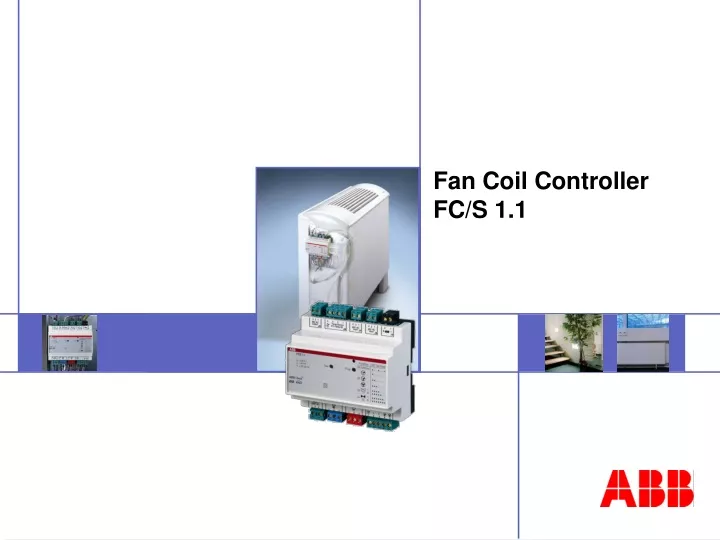
Fan Coil Controller FC/S 1.1. Fan Coil Controller, MDRC FC/S 1.1. Control of Fan Coil Units via EIB/KNX MDRC installation 6 modules width All connections: screw terminals Application: Heating and cooling with individual room temperature control Central boiler and cold water supply system.

E N D
Fan Coil Controller, MDRC FC/S 1.1 • Control of Fan Coil Unitsvia EIB/KNX • MDRC installation • 6 modules width • All connections: screw terminals • Application: Heating and cooling with individual room temperature control • Central boiler and cold water supply system
Structure of an HVAC system with fan coil units Fan coil units Hot water circulation loop Cold water circulation loop Boiler and cold water supply
Structure of a fan coil unit Switch box with controller Valves Fan Motor Drip tray Filter Heat Exchanger
Variants – Water Systems I 4-pipe version • Separate water circulation loops for hot and cold water
Variants – Water Systems II 3-pipe version • Separate inlet for hot and cold water • Common return flow
Variants – Water Systems III 2-pipe version • One water circulation loop only • Either hot or cold water depending on the time of the year or only cold water (heating via radiators)
Variants – Designs • Compact units (including housing): upright, wall mounting, or ceiling mounting • Built-in units (without housing): wall mounting, ceiling mounting, or floor mounting • Circulating air units / mixed air units
Fan Coil Controller, MDRC FC/S 1.1 Outputs • 1 output for heating1 output for cooling(for electromotive or electrothermal valve drives) • Output for fan motors with up to 3 speed levelsvia potential-free contacts
Fan Coil Controller, MDRC FC/S 1.1 Inputs • Temperature sensor TS/K 1.1 • 2 binary inputs 24 V AC for:- window contact- drip tray monitoring (condensated water) • Potentiometer Other connections • 230 V AC Power supply • 24 V AC Auxiliary voltage for binary inputs • EIB/KNX
Fan Coil Controller, MDRC FC/S 1.1 Operation Modes • Fan Coil / Convector (Heating and cooling)- Fan coil: Valve drive and fan control- Convector: only valve drive control • 2-pipe / 4-pipe version- 4-pipe version: 2 separat valves for heating and cooling (two water circulation loops)- 2-pipe version: 1 common valve for heating and cooling (one water circulation loops) (Valve is connected to heating output)
Fan Coil Controller, MDRC FC/S 1.1 Actual temperature • Room temperature- local via temperature sensor TS/K 1.1 (can be sent via EIB/KNX, cyclically or on change of value) - from room temperature controller via EIB/KNX (cyclically monitored) • Outside temperature- via EIB/KNX (cyclically monitored)- for adjusting of set temperature
Fan Coil Controller, MDRC FC/S 1.1 Setpoint values I • Base setpoint temperature (via parameter or communication object) • Setpoint adjustment(via EIB/KNX or local via potentiometer) • Optional: Setpoint correction depending on external temperature for cooling • Insensitive zone between heating and cooling
Fan Coil Controller, MDRC FC/S 1.1 Setpoint values II • Reduced heating / increased cooling setpoint temperature for:- standby mode- night setback • Temperature thresholds for frost and heat protection mode • Limit setpoint values for heating and cooling • Switching between comfort mode, standby mode and night setback via EIB/KNX
8 9 12 11 3 4 1 2 Fan Coil Controller, MDRC FC/S 1.1 Connections1. Power supply 230 V AC2. Cooling valve3. Heating valve4. Fan (up to 3 levels)5. EIB/KNX6.+7. 2 binary inputs 24 V AC8. Temp. Sensor + Potentiometer9. Auxiliary voltage 24 V AC for binary inputs10. Test push button11. Programming push button12. Programming LED / Test LED13. Test table 7 6 5 10 13