Download

1 / 55
800 likes | 2.11k Views
Les réseaux Industriels MODBUS. Introduction.

E N D
Introduction • Modbus is a communication protocol developed by Modicon systems. In simple terms, it is a way of sending information between electronic devices. The device requesting the information is called the Modbus Master and the devices supplying information are Modbus Slaves. In a standard Modbus network, there is one Master and up to 247 Slaves, each with a unique Slave Address from 1 to 247. The Master can also write information to the Slaves.
Topologie bus Nombre théorique d'abonnés 247. Peut-être plus faible suivant les constructeurs ainsi que par la limitation de la couche physique. Transmission en semi duplex, pas de médium particulier (paire torsadée, coaxial, fibre optique…) fixé en fonction des distances et des interfaces disponibles. Transmission en bande de base de 50 à 19 200 bits/s. RS232, RS422, RS485. Méthode d'accès par protocole maître – esclaves (question/réponse) Caractéristiques
I4 I3 I2 I1 MODBUS with a PLC millenium II (CROUZET) PLC system for the workshop O4 O3 O2 O1 Power supply PLC Inputs/outputs Modbus Interface
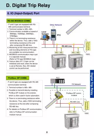
Modbus Serial line RS485 MODBUS Serial line RS485 is a low cost network using amaster/slave medium access with a transmission speed from 1,200 to 115 Kbits/s 7 6 5 4 3 2 1 Application Modbus Presentation Session Transport Network Master - Slave Link Physical RS485
Modbus TCP/IP MODBUS TCP/IP uses TCP/IP and Ethernet 10 Mbit/s or 100 Mbits/s to carry the MODBUS messaging structure. 7 6 5 4 3 2 1 Application Modbus Préeentation Session Transport TCP Network IP Link CSMA / CD ETHERNET V2 ou 802.3 Physical
Modbus Plus MODBUS PLUS is a higher speed network 1 Mbit/s token passing derivative that uses the MODBUS messaging structure. 7 6 5 4 3 2 1 Application Modbus Presentation Session Transport Network 802.4 Token passing Link Physical RS485
Deux modes de transmission, sont définis : Le mode RTU et le mode ASCII. Les modes de transmission doivent être identiques pour tous les participants à un même réseau. Le mode ASCII est une option. Les modes de transmission.
Address Function Data Checksum silence silence Modbus frame structure The Modbus frame structure is the same for requests (master to slave messages) and responses (slave to master messages). Modbus RTU Silence >= 3,5 characters Modbus ASCII : Address Function Data Checksum CR LF 0D Hex 0A Hex 3A Hex
Les trames RTU ne comportent ni entête, ni délimiteur de fin. La station réceptrice contrôle le temps séparant deux caractères consécutifs, s'il est supérieur à 3 caractères et demi, elle considère que le prochain caractère est un début de trame. Chaque octet (00 à FF), d'une trame RTU, est transmis suivant le format recommandé : 1 Bit de start, 8 bits de donnée, 1 Bit de parité, 1 Bit de Stop. Transmission en mode RTU
La parité est normalement paire par défaut. Il est possible de supprimer la parité, dans ce cas, il est recommandé de mettre deux bits de stop. (1 bit de start, 8 bits de donnée, 2 Bits de Stop). Une clé de contrôle de deux octets est ajoutée à la fin de la trame. C'est un CRC16 dont le polynôme générateur est g(X)=X16 + X15 + 1. Les deux octets du CRC sont transmis poids faible en tête. Le CRC est calculé sur l’ensemble des champs adresse, fonction et données. Transmission en mode RTU
Les trames sont émises avec un délimiteur de début "3A" (Code ASCII de ":") et un délimiteur de fin "0D 0A" (Codes ASCII de CR et LF) Chaque octet d'information (00 à FF) est codé sur deux octets « imprimables ». Transmission en mode ASCII
Transmission en mode ASCII Chaque caractère ASCII est transmis suivant l’un des deux formats : • Start, 7 bits de donnée, 1 Bit de parité, 1 Bit de Stop. • Start, 7 bits de donnée, 2 Bits de Stop. clé de contrôle: somme modulo 256 de tous les octets de la trame non encore codée en ASCII
Trame d’exception • Des trames d’exception sont prévues pour permettre la gestion du réseau et le traitement des erreurs. • 11 Caractères en ASCII. • 5 Octets en RTU 1 - Fonction inconnue. 2 - Adresse incorrecte. 3 - Donnée incorrecte. 4 - Esclave non prêt. 5 - Acquittement. 8 - Défaut d’écriture. Le code fonction retourné est celui de la commande avec le bit de poids le plus fort forcé à 1.
Le maître envoie la même demande à la station n°1 Champ adresse 01 Champ code 08 Champ données 00 00 61 62 Trame RTU : 01 08 00 00 61 62 48 72 Trame ASCII: 3A 30 31 30 38 30 30 30 30 36 31 36 32 33 340D 0A Calcul du LRC de la trame ASCII: somme des octets de la trame : 01+08+00+00+61+62=CC complément à deux :00-CC=34 LRC = 34 soit codé ASCII "33 34" Comparaison entre les deux modes
Exemple: Fonction 01 Cette fonction est utilisée pour la lecture de 1 à 2000 bits contigus dans un équipement distant. Exemple: Lecture de 20 bits de sortie à partir de l’adresse 20 20 (en décimal) se traduit par 14 en hexadécimal Dans le protocole, c’est l’adresse – 1 que l’on trouve dans le champ de données
Exemple: Fonction 01 L’état des sorties 27 – 20 est CD en hexa soit 1100 1101 en binaire. La sortie 27 est le MSB de l’octet, et la sortie 20 est le LSB
Mise en oeuvre RS232 – Liaison point à point (deux appareils) RS485 – Liaison multi points (plus de deux appareils)
Address Function Data Checksum Address field Valid slave device addresses are in the range of 0 ... 247 decimal. The individual slave devices are assigned addresses in the range of 1 ... 247. Value 0 is reserved for broadcast messages (no response). Request : A master addresses a slave by placing the slave address in the address field of the message. Response : When the slave sends its response, it places its own address in this address field of the response to let the master know which slave is responding.
Address Function Data Checksum Function field Valid codes are in the range of 1 ... 255 decimal. Request : The function code field tells the slave what kind of action to perform. Response : For a normal response, the slave simply echoes the original function code. For an exception response, the slave returns a code that is equivalent to the original function code with its most significant bit set to a logic 1.
Address Function Data Checksum Data field Valid codes are in the range of 0 ... 255 decimal. Request : The data field contains additional information which the slave must use to take the action defined by the function code. This can include items like register addresses, quantity of items to be handled, etc... Response : If no error occurs, the data field contains the data requested. If an error occurs, the field contains an exception code that the master application can use to determine the next action to be taken.
Address Function Data Checksum Checksum field Valid codes are in the range of 0 ... 255 decimal. Modbus RTU uses CRC : Cyclycal Reduncy Check (2 byte) Modbus ASCII uses LRC : Longitudinal Redundancy Check (1 bytes) Request : The checksum is calculated by the master and sends to the slave. Response : The checksum is re-calculated by the slave and compared to the value sent by the master. If a difference is detected, the slave will not construct a response to the master.
Frame exemple in RTU mode • Function code = 03 : Read Holding Registers Request : 1 byte 1 byte 2 bytes 2 bytes 2 bytes Slave Address Function code = 03 First word address Number of words to read CRC16 Response : 1 byte 1 byte 2 bytes 2 bytes 2 bytes 2 bytes Slave Address Function code = 03 Number of bytes read Value of the first word Value of the last word CRC16
Frame exemple in RTU mode • Function code = 06 : Write Single Register Request : 1 byte 1 byte 2 bytes 2 bytes 2 bytes Slave Address Function code = 06 Word address Value of word CRC16 Response : 1 byte 1 byte 2 bytes 2 bytes 2 bytes Slave Address Function code = 06 Word address Value of word CRC16
Frame exemple in RTU mode • Function code = 16 (décimal) : Write Multiple Registers Request : 1 byte 1 byte 2 bytes 2 bytes 1 byte 2 bytes 2 bytes Slave Address Function code = 16 First word address Number of words to write Number of bytes Value of the first word CRC16 Response : 2 bytes 1 byte 1 byte 2 bytes 2 bytes Number of words to write CRC16 Slave Address Function code = 16 First word address
Physical layer:New Modbus RS485 standard schematic 5 V Master 650 650 D1 120 120 1 nF 1 nF D0 Common Slave 1 Slave 2
Main characteristics resume Topology: Bus with line terminations Maximum distance:With RS485 : 1000 m without repeater Data rate: From 1,200 to 115 Kbits/s Max. no. of devices:With RS485 : 32 master included
Main characteristics resume Method of accessing the medium: Master slave Transmission method: Messaging Max. useful data size: 120 words Transmission security: LRC or CRC Start and stop delimiters Parity bit Continuous stream
MODBUS PROTOCOL (query/response) MASTER TRANSMIT RECEIVE TRANSMIT RECEIVE TRANSMIT RECEIVE TRANSMIT RECEIVE SLAVE 1 SLAVE 2 SLAVE N Protocol admit only one master and until 255 slaves with serial interface. Each frame as a particular number of bytes Each frame is coded Half duplex mode The master transmit a question and wait a response 2 slaves can’t speak together LABVIEW SESSION IRBID 2007
BUILD A FRAME (GENERAL) address ADR Function OP Datas DATA Control CRC16 4 fields are used to build a frame address field (1 byte) : Provide the numerous (1 to 255) for the slave concerned by the operation. ADR = 0 ; for a broadcast to all slaves. Function field (1 byte) : Provide the code for the operation. Datas field (n bytes) : Provide the address/datas for the slave concerned by the operation. Control field (2 bytes) : Word CRC16 add at the end of the message to secure the communication (Cyclic Redundancy Chehksum 16 bits). LABVIEW SESSION IRBID 2007
MODBUS PROTOCOL (broadcasting) For the broadcasting, the master send a message to all slaves units. Those ones execute it without response. LABVIEW SESSION IRBID 2007
BUILD A FRAME (READING BITS) Function 01h or 02h :reading request for n consecutive bits The master provide the address on 16 bits, of the first bit to read and the number of consecutive bits to read. ADR 01h address 1st bit to read bits number to read (1 to 640) CRC 1 byte 1 byte 2 bytes 2 bytes 2 bytes 0 ou 1 0 ou 1 start d0 d1 d2 d3 d4 d5 d6 d7 stop start d0 d1 d2 d3 d4 d5 d6 d7 stop Response to the reading request of bits (6 to 85 bytes) 1st byte read ADR 01h CRC bytes number (1 to 80) 1 byte 1 byte 1 byte 2 2 2 bytes 7 0 The frame… LABVIEW SESSION IRBID 2007
BUILD A FRAME (READING WORDS) Function 03h or 04h :reading request for n consecutive bytes The master provide the address on 16 bits, of the first byte to read and the number of consecutive words to read. ADR 03h CRC adr 1st word to read words number to read(1 - 128) 1 byte 1 byte 2 bytes 2 bytes 2 bytes Response to the reading request of words (7 to 261 bytes) 1st word read ADR 03h CRC bytes number (0 - 256) 2 bytes 1 byte 1 byte 1 byte 2 bytes LABVIEW SESSION IRBID 2007
BUILD A FRAME (WRITING BITS) Response to the writing request of bits(8 bytes) ADR 0Fh CRC address 1st bit to write bits number to write (1 to 800) 1 byte 1 byte 2 bytes 2 bytes 2 bytes Function 0Fh :writing request for n consecutive bits The master provide the address on 16 bits, of the first bit to write and the number of consecutive bits to write, the state of the bits. (frame size : 10 to 109 bytes) bytes number state of the bits ADR 0Fh CRC address 1st bit to write bits number to write (1 to 800) b ,...,b ,b ,...,b ,b ,... 1 byte 1 byte 2 bytes 2 bytes 2 bytes 1 byte 7 0 15 8 23 LABVIEW SESSION IRBID 2007