Download
1 / 16
160 likes | 300 Views
IBM PC Controlled Keypunch. Stan Paddock Computer History Museum July 13, 2008. Overview. The Computer History Museum (CHM) has restored and made operational an IBM 1401 computer system with the full memory complement of 16,000 BCD characters.

E N D
IBM PC Controlled Keypunch Stan Paddock Computer History Museum July 13, 2008
Overview • The Computer History Museum (CHM) has restored and made operational an IBM 1401 computer system with the full memory complement of 16,000 BCD characters. • At the current time, CHM does not have working card decks to assemble or compile any language. Some newly acquired magnetic tapes may yield such decks. • A software configuration has been developed to run on an IBM PC under Windows that will develop IBM 1401 code using the same input and output format as the IBM 1401 Autocoder program. • The problem this project addresses is that there is no path to get the punch card images from the IBM PC disk to actual real punched cards without having to manually punching the cards by hand.
Solution • The IBM keypunch has 13 control lines that go into the punch unit. These are for punches 0-9, -, + and (space) • By connection these lines to the keypunch signal ground, the requested characters will be punched and the card advanced. • One additional line is connecter to coil terminal 2 on relay 2 of the keypunch to cause a ‘release’ of the current card. • The power supply of the keypunch is not grounded, but left to float. • For this reason, and the protection of both the keypunch and the IBM PC, all interface connections are made via relay contacts.
High Level Design Measurement Computing USB-SSR24 USB-based solid-state 24 I/O module interface IBM 026 Keypunch IBM PC IBM 026 Keypunch Control Wires
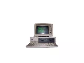
IBM PC Definition • The IBM PC is running Windows XP • The IBM PC must have a USB port available to connect the USB relay control box • The IBM PC must have a hard wired COM port to also connect the USB relay control box • The IBM PC needs to have the ROPE1401 software package installed. This was developed by and available from Ron Mak through the CHM • The IBM PC needs to have RmtPunch installed. This was developed by and available from Stan Paddock through the CHM
USB Relay Control Box • The relay control box is available from Measurement Computing • http://www.measurementcomputing.com/cbicatalog/cbiproduct_new.asp?dept_id=416&pf_id=1685&mscssid=0SL2ATXLXBV39KJ9AWMDQJ4JUMKFA765 • The ID number is USB-ERB24 and costs about $399.00 • The box has 24 SPDT 6A relays with external screw connections • The relays are addressable as: • First bank, 8 relays used for punches 9,8,7,6,5,4,3,2 • Second bank, 8 relays used for punches 1,0,-,+,(space),(release) • Third bank, 4 relays Used for green LEDs • Fourth bank, 4 relays Used for red LEDs
USB Relay Control Box Addition (1/3) • Believe or not, control of the keypunch is time critical • All of the punch control lines must be presented at the same time as the first one seen, which starts the punch cycle • All of the punch control lines must be cleared within 20ms or it will cause a double punch. • By using just the USB relay control box by itself, the punch data was 98.5% accurate. Not good enough. • Windows is not a real-time system. You cannot count on having all of the CPU time to your self. • A special circuit board was built that solved this problem.
USB Relay Control Box Addition (3/4) • Inputs to this board are: • Signal Ground from COM1: pin 5 of the IBM PC • Request To Send from COM1: pin 7 of the IBM PC • Data Terminal Ready from COM1: pin 4 of the IBM PC • Clear To Send from COM1: pin 8 of the IBM PC • Common of relays 1 to 16 on the USB relay controller box • Signal Ground from the IBM 026 keypunch (not frame ground) • COM1: pins 5 & 7 drive a transistor which in turn drives a SPDT relay. • The relay makes a connection across inputs 5 and 6. • The software is configures to raise the Request To Send line when data is being transmitted from COM1: • At 9600 baud, one byte takes 1ms. If you send out 10 characters, the Request To Send line will give you a 10ms pulse. Since this is done by hardware, this is very predictable regardless of the operating system or system loading
USB Relay Control Box Addition (4/4) • COM1: pins 5 & 8 are sent to the 026 keypunch to a relay contact. The relay contact is made only when there is a card registered. The IBM PC can sense the line so it will not attempt to punch when the cards run out. • The configuration left 8 relay connections left with no purpose. • There was also extra space left on the circuit board • There are eight LEDs installed on the circuit board controlled by the last 8 relays. • The software uses these LED to show the number of cards left to punch
Interface to IBM 026 Keypunch External DB-25 connection Internal wiring connection connection
RmtPunch Functionality • When initiated, RmtPunch will ask the user to select the card file to be punched. • RMT will process the file and identify the number of cards to be punched and the total number of columns to be punched. • If there is an error in the file, the error will be identified and the program will terminate. • If the data is valid, the user will be instructed to ready the keypunch and press a “P” for punch. Cards must be registered in the punch station and the “Auto Feed” switch on. Print is not necessary.
RMTPUNCH Screens Initial Screen
RMTPUNCH Screens Initial Screen File Selection Screen
RMTPUNCH Screens Running Screen
RMTPUNCH Screens Last Screen