Download
1 / 32
340 likes | 546 Views
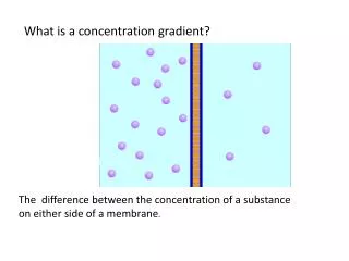
Impact of Doping Concentration Gradient and Spacer Thickness on Device Performance of UTB-SOI CMOS. Hannes Luyken CPR ND. Session 1.1: Transistor architecture and fabrication.

E N D
Impact of Doping Concentration Gradient and Spacer Thickness on Device Performance of UTB-SOI CMOS Hannes Luyken CPR ND Session 1.1: Transistor architecture and fabrication T. Schulz, C. Pacha, R. J. Luyken, M. Städele, J. Hartwich, L. Dreeskornfeld, E. Landgraf, J. Kretz, W. Rösner, M. Specht, F. Hofmann and L. Risch Infineon Technologies AG, Corporate Research Nano Devices, Otto-Hahn-Ring 6, D-81730 Munich, Germany ULIS 2003 Ultimate Integration of Silicon N e v e r s t o p t h i n k i n g .
Outline • Motivation for the ultra thin body (UTB)-SOI device concept • Simulation method • Impact of technology parameters on device performance - source/drain doping concentration gradient - sidewall spacer thickness - silicon thickness - supply voltages • Conclusions
Motivation for the ultra thin body (UTB)-SOI device conceptwith undoped channel region • Undoped channel region ÜIncrease in drive current • New gate materials ÜVth adjustment
Simulation method • green area: interconnects and wiring and geometrical aspects of gates • blue area: intrinsic device and substrate material • red area: Äcoupled device and circuit simulation
Device structure and technological parameters • No additional source/drain series resistances were chosen • NMOS and PMOS have the same structure apart from the different doping sequence
Simulation scheme and circuit structure • 2 Inverter 4 MOSFETs (n1, p1, n2, p2) • Additional R and C RC-load C-wiring • Input pulse (1ps) Delay between VOUT_1 and VOUT_2
Impact of technology parameters on inverter delay - source/drain doping gradient @ constant spacer
Impact of technology parameters on inverter delay - source/drain doping gradient @ constant spacer • Where is the effective / metallurgical channel length ? • Leff as figure of merit vanish
Impact of technology parameters on inverter delay - source/drain doping gradient @ constant spacer • Where is the effective / metallurgical channel length ? • Leff as figure of merit vanish • Is a relaxed doping gradient of 10 nm / decade sufficient ?
IOFF and ION versus doping gradient @ constant spacer • Steep doping profiles Ü suppress short channel effects
IOFF and ION versus doping gradient @ constant spacer • Steep doping profiles Ü suppress short channel effects • Shallow doping profiles Ü flood the channel with dopants • In most cases spacer thickness of 10nm is too thin
Impact of technology parameters on inverter delay - sidewall spacer thickness @ constant gradient
Impact of technology parameters on inverter delay - sidewall spacer thickness @ constant gradient • What is the optimal spacer thickness ?
Impact of technology parameters on inverter delay - sidewall spacer thickness @ constant gradient • What is the optimal spacer thickness ? • Thinner sidewall spacer Ü increase short channel effects • Thicker sidewall spacer Ü increase inverter delay
IOFF and ION vs. spacer thickness @ constant gradient • Thin spacer Ü leakage current increase
IOFF and ION vs. spacer thickness @ constant gradient • Thin spacer Ü leakage current increase • Thick spacer Ü drive current decrease • Best case for L=50nm LOP device is 20-25nm spacer thickness
Comparison with (bulk) roadmap trend:sidewall spacer thickness correlate with doping gradient • State of the art: 50nm spacer thickness, 5nm/decade abruptness
Impact of technology parameters on inverter delay - combination of spacer thickness and doping gradient
Impact of technology parameters on inverter delay - combination of spacer thickness and doping gradient
Impact of technology parameters on inverter delay - combination of spacer thickness and doping gradient • Compensation of spacer thickness and doping gradient • New figure of merit: doping concentration @ gate corner
IOFF and ION versus different spacer / doping gradient • HP-device and LOP-device specs achievable • IOFF spec for the LSTP-device demand thicker spacer
IOFF and ION versus different spacer / doping gradient • HP-device and LOP-device specs achievable • IOFF spec for the LSTP-device demand thicker spacer • For the presented doping profiles 10 nm/decade is the better choice
Transfer and output characteristicsfor different spacer thickness and doping gradient • Figure of merit: doping concentration 1E19cm-3 @ gate corner • Devices with different doping profiles but same driver performance • Increase of GIDL-current due to steeper doping concentration gradient
Conclusions • Doping concentration gradient and spacer thickness can compensate each other as design parameter. • Source/Drain doping concentration at the gate corner is an accurate figure of merit instead of Leff. • With a steeper doping concentration gradient there is no influence on the driver performance but a significant off-current due to the increase of the GIDL-current occurs. • HP- and LOP-devices can meet the roadmap targets but LSTP-devices are much harder to implement.
Impact of sidewall spacer thickness in combination with doping gradient • figure of merit: doping concentration @ gate corner = 1E18cm-3
Impact of sidewall spacer thickness in combination with doping gradient • figure of merit: doping concentration @ gate corner = 1E18cm-3 • compensation of spacer thickness and doping gradient depends also from the source / drain doping concentration level (here 1E20cm-3)
Silicon film thickness replace doping concentration as figure of merit • Bulk: • SOI: • DG: