Download
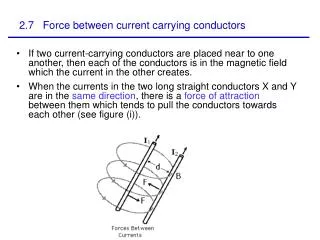
1 / 19
190 likes | 298 Views
Magnetic Force on Current Carrying Wires. Curtis H. Choi Joseph Wassei Jonathan Po Physics 2B Laboratory Presentation Costantino Las Postias College April 25,2003. Background. History of Magnetism Magnesia “ Lodestones ” attract pieces of iron Chinese Compasses made of lodestones

E N D
Magnetic Force on Current Carrying Wires Curtis H. Choi Joseph Wassei Jonathan Po Physics 2B Laboratory Presentation Costantino Las Postias College April 25,2003.
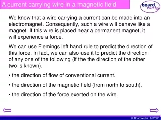
Background • History of Magnetism • Magnesia • “Lodestones” attract pieces of iron • Chinese • Compasses made of lodestones • William Gilbert (1500’s) • Artificial magnets, by rubbing lodestone and iron • “electrics”attracting various materials (Amber (G)) • Static electrical attraction to a magnetic attraction • Electrical attraction may be transmitted through an object
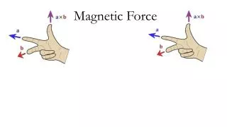
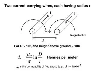
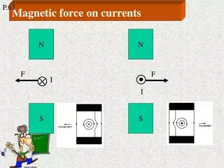
Background • History of Magnetism cont. • Hans Christian Ørsted (Physicist) • Accidental discovery re-linking electric and magnetic theory • Ampére (Mathematician) • Source of magnetic field is electric current, as the source of an electric field is an electric charge • Magnetic field (B) around a wire is proportional to the current flowing through the wire • Right hand rule • Two current-carrying wires attract/repel depending on direction of current
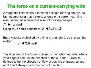
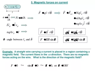
Theory • Interaction between a moving charge and a magnetic field can be described as followed: F=qvBsinθ(Eqn. 1) q= magnitude of moving charge, v= velocity B= magnetic field • Extended using cross-sectional area A and Length L carrying current I F= qvdB (Eqn. 2) vd=drift velocity
Theory • Since V=AL & the number of carriers=nAL the magnitude of total magnetic force on a wire with length L is: F=(qvdB)(nAl) (Eqn. 3) • Since I=nqvdA, “F” may be expressed: F = ILBsinθ = ILB (Eqn. 4 & 5) • Assumptions made in our experiment: none of the electrons escape into the atmosphere, also neglect all forces on magnetic holder other than gravitation and electrical (magnetic)
Experimental Arrangement • Obtain the following equipment • Basic Current Balance and Accessory • Quadruple-Beam Gram Balance • DIGI Power Supply • DMM • Patch cords
Experimental Arrangement Assemble apparatus (used in Part A ~ C)
Experimental Arrangement • Part A • Assemble apparatus • Determine and record the mass of the magnet holder and magnets with no current flowing (m0). Magnet holder Magnets
Experimental Arrangement • Part A • Assemble apparatus • Determine and record the mass of the magnet holder and magnets with no current flowing (m0). • Measure the new “mass” of the magnet assembly in different current settings (0.5amp ~ 2.0amp increasing the current in 0.25 increments).
Experimental Arrangement: Part B • Part B • Determine and record the length of the conductive foil on the current loop (L). • Determine the new “mass” of the magnet assembly at 2.0amps current and record it as m(L). • Subtract m0 from m(L) and record as F(L). • Repeat the above steps with all the other current loops.
Experimental Arrangement • Part C • Mount a single magnet in the center of the holder. • Determine the mass of the magnet assembly without current flowing and record as m(n). • Set the current to 2.0 amps. Determine the new “mass” of the magnet assembly and record it as m(n,c). • Subtract m(n) from m(n,c) and record the difference as F(n).
Experimental Results • This apparatus was used in Part A: Force vs. current, Part B, Force vs. length of wire, and Part C: Force vs. magnetic field. • Magnetic holder weight(m0)= .1614 Kg Quadruple-beam balance Current loop Main unit Magnetic holder
Part A: Force vs. Current • The equation of the graph is Y= .0002x - 2E-6. • The slope of the line was found to be .0002 L*T. • The slope of the line is LB from the equation (F/I)=LB. • This equation tells us that if the current increases so does the force acting on the wire.
Part A: Force vs. Current • The equation of the graph is F = s*I + F0 • The slope of the line is s = B*L = 2.xx(10-4) N/A • For L = 2.00 cm, B = 0.076 T
Part B: Force vs. Length of Wire • The equation of the graph is Y=.0432x - .0004. • The slope is .0432 A* T. • The current was 2.0 Amps • The slope of the line is IB from the equation (F/L)=I*B. • As length of wire increases so does force acting on the wire. • Equation: • slope=B*I • B= .0432/2= .0216 T
Part C: Force vs. Magnetic Field • The equation of the graph is y= 7E-7x + 4E-5. • The slope of the graph is 7E-7 N per magnet. • As the number of magnets inc. so does the Force in the magnetic field.
Errors • Possible errors in this experiment are: • The quadruple-beam balance was not calibrated correctly. • Length of the conductive wire measured might have been measured incorrectly.
Conclusion • The magnetic field was found to be .0216 T using the equation slope = B*I • It was found that as the current, number of magnets, and the length of the conductive foil inc so does the force in the magnetic field.
Magnetic Force on Current Carrying Wires Curtis H. Choi Joseph Wassei Jonathan Po Physics 2B Laboratory Presentation Costantino Las Postias College April 25,2003.