Download
1 / 16
160 likes | 247 Views
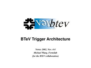
Fault Tolerance Issues in the BTeV Trigger. J.N. Butler Fermilab July 13, 2001. Outline. Brief Description of BTeV and of the Trigger The fault tolerance issue

E N D
Fault Tolerance Issues in the BTeV Trigger J.N. Butler Fermilab July 13, 2001
Outline • Brief Description of BTeV and of the Trigger • The fault tolerance issue • Our approach to fault tolerance – the Real Time Embedded System Project – RTES (Vanderbilt, Illinois, Syracuse, Pittsburgh, Fermilab) – a collaboration of computer scientists and physicists
Key Design Features of BTeV • A dipole located ON the IR, gives BTeV TWO spectrometers -- one covering the forward proton rapidity region and one covering the forward antiproton rapidity region. • A precision vertex detector based on planar pixel arrays • A vertex trigger at Level I which makes BTeV especially efficient for states that have only hadrons. The tracking system design has to be tied closely to the trigger design to achieve this. • Strong particle identification based on a Ring Imaging Cerenkov counter. Many states emerge from background only if this capability exists. It enables use of charged kaon tagging. • A lead tungstate electromagnetic calorimeter for photon and p0 reconstruction. • A very high capacity data acquisition system which frees us from making excessively restrictive choices at the trigger level
Schematic of Trigger phi 0 phi 1 phi 2 Quadrant Processor Board phi 3 phi 0 Trigger phi 4 phi 5 phi 7 Vertex Farm 50 m phi 6 (T%4)=0 One Board Per Station Quadrant 124 Boards 992 Cpu’s phi 7 phi 31 raw hits tracks hitsegments 4 farms 256 CPU’s station 1 quadrant (T%4)=0 5 cm Track Farm phi 7 (T%4)=1 (T%4)=2 (T%4)=3 36 pixel chips station 31 32 farms 2048 CPU’s Detector Station 3 layers Note that there are about 3000 processors in the L1 Trigger
Global Level I and Level 2/3 • Global Level 1 is another processor farm – possibly about 64 CPUs – to process the vertex trigger, the muon trigger (another processor farm) and other ancillary triggers. It manages prescales and controls deadtimes, supports multiple trigger lists. • There is also a large --estimated 3000 CPU farm of processors, probably running LINUX, which does the Level 2/3 trigger. • Important considerations for efficiency • Events do not have fixed latency anywhere. There is a wide distribution of event processing times even within a given Level • Events are not processed in time ordered fashion
The problem stated • From a recent review of the trigger • “Regarding the robustness and integrity of the hardware and software design of the trigger system, these issues and concerns have only begun to be addressed at a conceptual level by BTeV proponents … Given the very complex nature of this system where thousands of events are simultaneously and asynchronously cooking, issues of data integrity, robustness, and monitoring are critically important and have the capacity to cripple a design if not dealt with at the outset. It is simply a fact of life that processors and processes die and get corrupted, sometimes in subtle ways. BTeV has allocated some resources for control and monitoring, but our assessment is that the current allocation of resources will be insufficient to supply the necessary level of "self-awareness" in the trigger system …Without an increased pool of design skills and experience to draw from and thermalize with, the project will remain at risk. The exciting challenge of designing and building a real life pixel-based trigger system certainly has the potential to attract additional strong groups.”
Main Requirements • The systems must be dynamically reconfigurable, to allow a maximum amount of performance to be delivered from the available, and potentially changing resources. • The systems must also be highly available, since the environments produce the data streams continuously over a long period of time. • To achieve the high availability, the systems must be • fault tolerant, • self-aware, and • fault adaptive. • Faults must be corrected in the shortest possible time, and corrected semi-autonomously (i.e. with as little human intervention as possible). Hence distributed and hierarchicalmonitoring and control are vital. • The system must have a excellent life-cycle Maintainability and evolvability to deal with new trigger algorithms, new hardware and new versions of the Operating System
Special Requirements • We want to be able to dynamically devote portions of the system to testing new algorithms or hardware • We want to be able to dynamically allocate portions of the L2/L3 farm to reconstruction and analysis (There will be a huge amount of disk on the system to retain data for months) • We change modes during a “store” from alignment to normal operation and also to running special diagnostics for the detector
The Proposed Solution Figure 2 Bi-Level System Design and Run Time Framework – System Models use domain-specific, multi-aspect representation formalisms to define system behavior, function, performance, fault interactions, and target hardware. Analysis tools evaluate predicted performance to guide designers prior to system implementation. Synthesis tools generate system configurations directly from the models. A fault-detecting, failure mitigating runtime environment executes these configurations in a real-time, high performance, distributed, heterogeneous target platform, with built-in, model-configured fault mitigation. Local, regional, and global aspects are indicated. On-Line cooperation between runtime and modeling/synthesis environment permit global system reconfiguration in extreme-failure conditions.
The Design and Analysis Environment • Modelling • Information/Algorithm Data Flow Modelling • Target Hardware Resource Modelling • System Detection and Fault Mitigation Modeling • System Constraint Modelling • Analysis • Synthesis • Design Alternative Resolution, Partitioning and Processor Allocation • System Configuration Generation • Operation and Fault Manager creation and configuration Based on an approach called Model Integrated Computing. It will be used both as a design and simulation tool and for analysis and fault modelling during running
Run Time Environment • Operating System for DSPs and INTEL UNIX systems • Runtime Hierarchy • Very Lightweight Agents – simple software entities that expose errors in DSP kernel behavior • Adaptive, Reconfigurable and Mobile Objects for Reliability (ARMORs) at the process level • Hierarchical Detection and Recovery • Node level • Regional Level(s) • Global • Feedback with modeling environment • System Validation through software based fault injections • Collection of Data for Creating and Validating New Fault Models
1.Add, remove, replace elements 2.Provide Communication service to rest of hierarchy The Lowest Level Figure : (a) ARMOR architecture,(b) Embedded ARMOR ELEMENTARY DETECTION AND RECOVERY SERVICES Figure : ARMOR Error Detection and Recovery Hierarchy
Other Aspects • Run Management/control • Persistent Storage (resource management, run history). Although faults may be handled at any level of the hierarchy, fault and mitigation data are always passed to the highest level so the experiment can track all conditions affecting the data • User interface/diagnostics/automatic problem notification • Application code – the application code and physics algorithms will use the same underlying infrastructure of the fault tolerance system. ARMOR has an API for this purpose.
Funding Year Design Environment Milestone Run time System Milestone FY1Q1/2 Modeling language and env (preliminary) Specify Interface to Run time Env. Design of overall runtime system hierarchy (ARMOR + VLAs) FY1Q3/4 Synthesis of operations and Fault managers DSP and LINUX Synthesis Design and implementation of VLA & ARMOR prototypes FY2Q1/2 Modeling language and env Design space (preliminary) Communication structure between VLAs and the levels above FY2Q3/4 Synthesis of performance simulator Synthesis of all operations mgrs (final) Hardware synthesis Detection and recovery in Layer 1 of ARMOR. Study Dynamic load-balancing (DL) FY3Q1/2 Modeling language and env (final) Design space Detection and recovery in Layer 2 of ARMOR; Study DL. FY3Q3/4 Synthesis to Diagnosability tool Synthesis to performance simulator (final) Detection and recovery in Layer 3 of ARMOR; Study DL. FY4Q1/2 Design space (final) Full scale Runtime Environment test FY4Q3/4 Synthesis to Reliability tool Synthesis to Diagnosability tool (final) Large scale evaluation on BTeV hardware and revision FY5Q1/2 Synthesis to Reliability tool (final) Final evaluation on BTeV hardware Project Schedule
Conclusion • BTeV agrees that fault tolerance may be the most difficult issue in successful of the trigger • BTeV has an architecture, a plan, and a project to produce a fault tolerant, fault adaptive system • The work done on this project should have wide applicability to large parallel systems with very high availability requirements