Download

1 / 54
570 likes | 800 Views
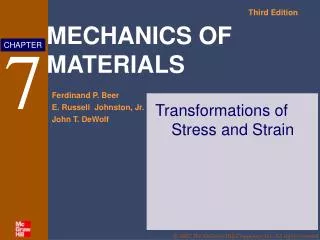
Chapter 7 Transformations of Stress and Strain. 7.1 Introduction. Goals: determine: 1. Principal Stresses 2. Principle Planes 3. Max. Shearing Stresses. 3 normal stresses. -- x , y , and z. General State of Stress.

E N D
Chapter 7 Transformations of Stress and Strain
7.1 Introduction Goals: determine: 1. Principal Stresses 2. Principle Planes 3. Max. Shearing Stresses 3 normal stresses -- x, y, and z General State of Stress 3 shearing stresses -- xy, yz, and zx
Plane Stress condition 2-D State of Stress Plane Strain condition A. Plane Stress State: z = 0, yz = xz = yz = xz = 0 z 0, xy 0 B. Plane Stress State: z = 0, yz = xz = yz = xz = 0 z 0, xy 0
Thin-walled Vessels In-plane shear stress Shear stress Out-of-plane shear stress
Max. x& y (Principal stresses) Max. xy
After rearrangement: (7.1) (7.2) Knowing
Eqs. (7.1) and (7.2) can be simplified as: (7.5) (7.6) Can be obtained by replacing with ( + 90o) in Eq. (7.5) (7.7)
1. maxand min occur at = 0 2. max and min are 90o apart. max and min are 90o apart. 3. max and minoccur half way betweenmax and min
7.3 Principal Stresses: Maximum Shearing Stress Since max and min occur at x’y’ = 0, one can set Eq. (7.6) = 0 (7.6) It follows, (a) Hence, (b)
Substituting Eqs. (a) and (b) into Eq. (7.5) results in max and min: (7.14) This is a formula of a circle with the center at: and the radius of the circle as: (7.10)
The max can be obtained from the Mohr’s circle: Since max is the radius of the Mohr’s circle,
Since max occurs at 2 = 90o CCW from max, Hence, in the physical plane max is = 45o CCW from max. In the Mohr’s circle, all angles have been doubled.
Sign conventions for shear stresses: CW shear stress = and is plotted above the -axis, CCW shear stress = ⊝ and is plotted below the -axis
7.5 General State of Stress – 3-D cases Definition of Direction Cosines: with
Dividing through by A and solving for n, we have (7.20) We can select the coordinate axes such that the RHS of Eq. *7.20) contains only the squares of the ’s. (7.21) Since shear stress ij = o, a, b, and c are the three principal stresses.
7.6 Application of Mohr’s Circle to the 3-D Analysis of Stress A > B > C = radius of the Mohr’s circle
Hoop Stress 1 (7.30)
Longitudinal Stress 2 Assuming the end cap or the fluid inside takes the pressure Solving for 2 (7.31) Hence
7.8 Fracture Criteria for Brittle Materials under Plane stress
1 2
1 2
1 2
1 2
1 2