Download
1 / 95
1.1k likes | 1.79k Views
Solvent Extraction Liquid-Liquid Extraction Prepared by Dr.Nagwa El- mansy Cairo University Chemical Engineering Department. Liquid-Liquid Extraction

E N D
Solvent ExtractionLiquid-Liquid ExtractionPrepared by Dr.Nagwa El- mansyCairo UniversityChemical Engineering Department
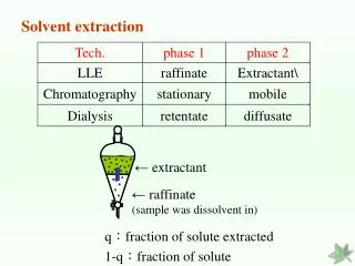
Liquid-Liquid Extraction “The separation of the components of a liquid mixture by treatment with a solvent in which one or more of the desired components is preferentially soluble is known as liquid–liquid extraction.” In this operation, it is essential that the liquid-mixture feed and solvent are at least partially miscible ( some time completely immiscible).
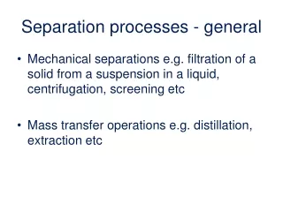
The mechanism of extraction involves two steps which are:- First Step:- Contacting Step:- Bringing the feed mixture and the solvent into intimat contact. Second Step:- Separation Step:- Separation of the resulting two phases. It is done by:- distillation, evaporation, Crystallization.
It is possible to combine first two stages into a single piece of equipment such as a column which is then operated continuously. Such an operation is known as differential contacting. Liquid–liquid extraction is also carried out in stage-wise equipment, the prime example being a mixer–settler unit in which the main features are the mixing of the two liquid phases by agitation, followed by settling in a separate vessel by gravity.
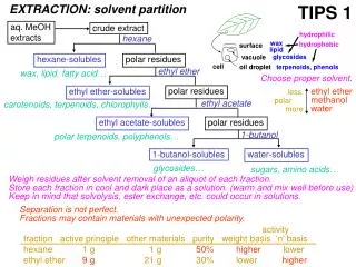
Applications of liquid-liquid extraction in petroleum Field:- 1- Removal of aromatics from Kerosene (Edeleanu Process) , It is one of the most important processes for refining Kerosene which improves the smoke point of Kerosene and Jet fuels by removing the aromatics content by Liquid sulphur dioxide.(Smoke point is the temperature at which it gives off smoke). 2-Removal of asphaltenesfrom lube oil which cause friction by using propane as a solvent. 3-Dewaxing of lube oil by using propane as a solvent. 4-Improving kinematic viscosity index (KVI) of lube oil
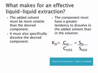
By removing aromatics and naphthens using phenol or furfural. [KVI measures the variation of viscosity with temperature. Paraffin has high (KVI) so presence of aromatics decreases(KVI)]. ( KV = µ/ρ = --- cm2/sec = stock ) Separation Factor (Selectivity) :- β
β = It is a measure of effectiveness of separation. The solvent is said to be effective or selective when β exceeds unity. The higher the selectivity the higher the separation.
Choice of solvent:- 1- High selectivity ( high β→ high yA/xA and low yB/xB) 2-Easy to be recovered. 3-Density:- The higher the density difference between Extract and raffinate the easier the segregation of both Phases. 4-Surface tension:- The larger the surface tension the higher the power needed to mix the two liquids with the solvent but the easier the segregation. 5- Other criteria:- non-corrosive , chemically stable , non-toxic , low viscosity , low vapor pressure.
Equilibrium Relations:- In liquid-liquid extraction we have three component system:- 1- solute (A)→liquid. 2- Inert (B)→liquid. 3- Solvent (S)→liquid. Representing the three component system on right angle triangle as follows :-
Types of phase diagram = Solubility diagram = Ternary diagram. Two main diagram :- A- Closed Ternary System:-
Methods of Operation(Types of contact):- • Simple Single Stage:-
Continuous contact(packed or spray columns) in liquid-liquid extraction:- In continuous contact using packed column, one of the phases is dispersed into the other phase and allowed to flow counter currently past the other phase(either up- wards or down-wards). Separation of the phases is not accomplished until the outlets are reached. Since contacting and separation do not take place at a number of discrete stages, equilibrium conditions are never reached with this type of equipment. The effectiveness of a continuous contact tower, may be expressed as:-
Height of packing = (number of stages) x (height equivalent to theoretical stage). H = n x HETP Where, HETP :- It’s the height of packing make the same separation of an ideal stage i.e two stream leaving are in equilibrium. No. of stages is calculated by the same methods of stage-wise contact
Performance of a given number of stages:- In many practical problems, the extraction equipment with known number of stages is already available and It’s required to find out the composition of the extract and raffinate streams obtained when using a certain (S/F) ratio or to find out the composition of extract(y1) or raffinate (xn). A- When(S/F) ratio is known, the products compositions are calculated as follows:- No.of stages = √ , (S/F) = √ , xn = ? , y1 = ? 1- Locate M according to the given (S/F).
2- Assume xn on raffinate locus. 3-Extend xnM to obtain y1 on the extract locus. 4- Obtain R at the intersection of x0y1 , xnyn+1 and proceed to obtain number of theoretical stages. 5- If the no. of stages founds corresponds to the specified no., the assumption of xn is correct and correspond to this composition (xn). If → n calculated > or < n given , a new xn is assumed. 6-The same procedure is repeated until the assumed xn yield the specified no. of stages. 7- y1 is obtained by connecting xnM and extend to cut extract locus at y1.
B-When the composition of the product raffinate stream is known, the problem will be to calculate the amount of solvent and the corresponding extract composition. Given:- xn = √ , no. of stages = n = √ , (S/F) = ? , y1 = ? , yn+1= √. • The trials procedure goes along the same line of material balance (position of point M). • The number of stages obtained is plotted against (S/F) • The required amount of solvent for the given no. of stage is obtained from the curve.
The correct M point is obtained . • Connect xn with M then extend to cut the extract locus at y1.
Minimum solvent requirements:- As the (S/F) ratio decreases:- 1- Number of stages increases. 2-y1 increases to y1’ and y1” . 3- M moves from M’ and M”. 4- R moves from R’ and R’’ i.e slopes of M.B lines range from -ve to ∞ to +ve. 5- For ∞ no. of stages , same minimum solvent requirements and maximum extract conditions. (S/F) min → ∞ no. of stages →y1 max
When tie line (xi , yi) coincide with operating line (xi ,yi+1) With R {pinch occur when extension of tie line passes Through x0 R}.
The conditions of minimum solvent requirements may be plotted on x-y diagram, the coincidence of a tie line and a material balance line on polar plot ,meaning that yi = yi+1 →the operating line and equilibrium curve having a common point. As S/F is reduced the operating curve moves from position(1) to (2) and(3) getting nearer to the equilibrium curve until it cuts it or touches it (position(3)) which corresponds to minimum solvent requirements and maximum extract composition(y1max) as shown in the following Figure.
Optimum (S/F) ratio:- When designing a new extraction battery the number of stages and (S/F) ratio are unknown. The optimum conditions of no. of stages and (S/F) ratio is determined as (S/F) increases, no. of stages decreases , but capacity of equipment to handle the increasing amount of solvent increases. As (S/F) increases the solution become more dilute which increase the cost of solvent removal unit.
Intermediate Feed:- In many cases mixtures consisting of same components but having different compositions are produced from various parts of a plant and have to be separated by solvent extraction to give the same terminal stream compositions. Three alternatives may be used:- 1- Each mixture is extracted in a separate apparatus. 2- All mixtures are put to gather and then extracted in one and the same apparatus. 3-Each feed is introduced at the proper stages of one and the same extraction equipment.
The last solution is the most economic and corresponds to lower number of stages. The feed stream richer in solute is introduced at stage(1) while the other feed which contains less amount of solute is introduced at later stages so that the composition of each feed is closest to the composition of the raffinate stream to which it is added.
Extract with reflux:- The maximum composition of extract product from Countercurrent multi-stage(y1max) occurs when the (S/F)min is used. This maximum composition at best situation at the end of the tie line passing through feed point, and even in that case an ∞ no. of stages is required . In practice it is always desirable to have an extract as rich as possible in the solute, richer than the composition of a layer in-equilibrium with the liquid feed. This could be possible by using “Enriching with reflux” or “Extract reflux” .