Download
1 / 17
170 likes | 290 Views
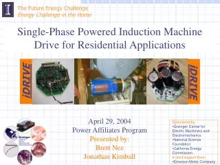
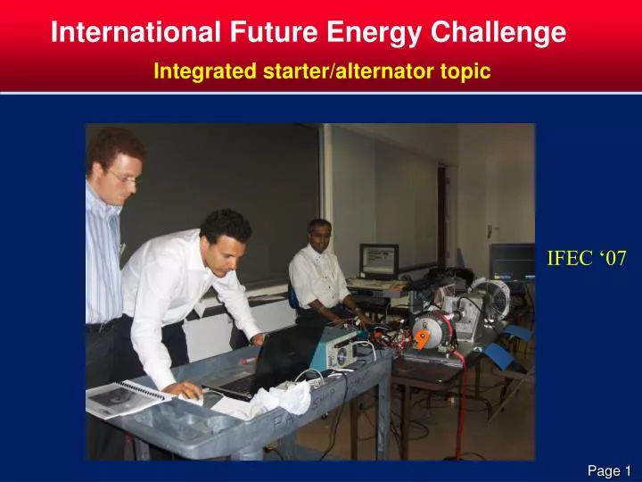
International Future Energy Challenge. Integrated starter/alternator topic. IFEC ‘07. Program Vision. Encourage development of technologies to bring dramatic improvements to low-cost 4-Q ASMD for integrated S/A application.

E N D
International Future Energy Challenge Integrated starter/alternator topic IFEC ‘07
Program Vision • Encourage development of technologies to bring dramatic improvements to low-cost 4-Q ASMD for integrated S/A application. • Incorporate practicality, manufacturability, affordability into competition process • Improve undergraduate education through development of innovative team-based solutions to complex problems
Technical Goals Figure 1. Functional Block Diagram of Test Set up
Technical Goals Mechanical Interface It is very important to have proper mounting and accurate alignment for safe operation of the whole set up. MUT mounting dimension should be in accordance with NEMA 56 frame size for foot mounting configuration. MPC test set up shall have matching dimensions to couple MUT confirming NEMA 56 frame size with foot mounting configuration. It is very important to observe these dimensions and verify that MUT dimensions match NEMA 56 frame size because any deviation may cause the MUT not to mount on MPC test set up. Such a situation may lead to being unable to test the MUT.
Technical Goals Figure 2. Electrical Interfacing
Technical Goals Electrical Interface: Assuming screw type terminal strips on prototype , these connections will be flying leads without any termination with appropriate cable size suitable to the power ratings. Please notify us immediately if competition specifications are otherwise for these electrical interfacing. DC bus voltage monitoring and control and brake IGBT/MOSFET are part of the prototype. . Input power supply shall have a current limit set to 20 ampere in order to protect against higher current under any adverse situation.
Technical Goals Speed profile for testing
Technical Goals • Test Methodology • There are three key areas of qualitative assessments: • Capability to start under 30 Nm load as starter • Reach the speed up to 3000 RPM as starter • Smoothly transition from starter to generator and charge • the batteries at 3000 rpm
Technical Goals Durability Test At the end of the day, all qualified hardware will be tested for durability. Fan blades may be mounted on the shaft to provide a nominal load. The motor will start from rest. The set up will be observed for 10 minutes to ensure safety and then will be left to run for about 30 minutes at the least. There will be no measurements/data acquisition/monitoring of these systems during durability test. The only protection to the set up will be the individual circuit breaker on the input power supply to each UUT. Finalists are recommended to verify their set up for such continuous run during their trials to ensure everything runs as planned at the time of final competition.
Judging • Judges will be experts from machine/drive industry • Design, operating documentation, test results, presentation, final report (including cost analysis) all considered • Development of point structure requires team participation
Rule Issues • Repair or maintenance work on hardware on site must be approved by judges • Units with major failures or obvious severe shipping damage may not be approved for testing • Once at MPC, hardware may not be taken off site • Appeals of rulings can be made to full judging committee – their decisions are final • Teams must follow safety regulations established by MPC and IFEC.
Prizes • Highest in team scoring will have detailed cost evaluation by industry experts • Expected prizes include $10k grand prize, and several category prizes ($5k/prize). • There is an design innovation award for creativity in design and control of ASMD. This award will be presented at IECON 2009 (Portugal).
A Few Points to Remember • Suggested Policy Points: • Students to work at least in pairs. • When full ac wall potential is in use, a faculty member or TA must be present. At least two people must be present. • No food or drink at lab benches.
A Few Points to Remember • Shock hazards exist in any labs. • Most likely problems are with spilled drinks or careless wiring. • Loose clothing and neckties are a problem when motors are used. • It only takes a watt to make small parts hot. • Often metal cases are live.
A Few Points to Remember • Serious power electronics work – • Safety glasses • Fire extinguishers • A safety plan, to include circuit protection
A Few Points to Remember • Turn power off when making circuit changes. • Keep a tight, neat setup. (It is safer, easier to debug, and just plain works better.) • Treat part cases as live or hot. • When in doubt, shut power off. • If it doesn’t work, it probably isn’t the instrument.
A Few Points to Remember • Equipment damage is a common safety issue. • Problem areas: • Grounding. Students often don’t understand limitations of grounded probes or sources. • Ratings. Do instrument ratings match the signal?