Download
1 / 17
170 likes | 312 Views
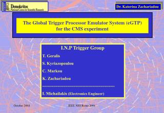
The Global Trigger Processor Emulator System (GTPemu) for the CMS experiment. Dr. Katerina Zachariadou. I.N.P Trigger Group T. Geralis C. Markou S. Kyriazopoulou K. Zachariadou I. Michailakis ( Electronics Engineer) M. Petrou (student). 3D view of the CMS - DAQ system.

E N D
The Global Trigger Processor Emulator System (GTPemu) for the CMS experiment Dr. Katerina Zachariadou I.N.P Trigger Group T. Geralis C. Markou S. Kyriazopoulou K. Zachariadou I. Michailakis (Electronics Engineer) M. Petrou (student) EESFYE-Chios
3D view of the CMS - DAQ system In the CMS Data Acquisition System, the Global Trigger Processor (GTP) calculates, for every beam crossing (25ns), up to 128 different trigger conditions and combines them to a Level-1 Accept signal. EESFYE-Chios
RTP TPG FES LV1 TTC FED surface sTTS aTTS FRL GTPemu LV1A (*8) RCN RU FRL BCN BDN FED Builder BU EVM (*8) The GTPemu system in the CMS-DAQ The L1A signal is sent via the Timing, Trigger and Control (TTC) optical network to all the Front-End Drivers (FED) of the sub-detectors and to the Event Manager (EVM). Furthermore, the GTP controls the delivery of Level-1 Accept signals according to feedback signals through the Trigger Throttling System (TTS). EESFYE-Chios
RTP TPG FES LV1 TTC FED surface sTTS aTTS FRL GTPemu LV1A (*8) RCN RU FRL BCN BDN FED Builder BU EVM (*8) The GTPemu system in the CMS-DAQ • testing the performance of the DAQ components during development (Preseries) • testing the performance of the DAQ system in run conditions. (The GTPemu will be part of the final system running in parallel with the GTP system) • during the DAQ system installation in the surface, the GTPemu will be used to decouple the LV1 system (underground area) from the readout system (surface) EESFYE-Chios
Front Rear B E D C F A The GIII-board The GTPemu is based on a generic, PCI 64bit/66 MHz board (GIII) . GIII is plugged into a PC (Linux), (controls the GTP via user’s interface processes) Data are transferred into a second GIII card (receiver)via the SLINK-64 protocol and are retrieved by a readout software. • FPGA (APEX –Altera • 32 MB SDRAM (133Mhz) • C. 1 MB Flash • D. S_Link64 connectors (data transmission) • E. User connectors • F. PCI interface for 32b/64b @33/66MHz GTPemu board Data Receiver board SLINK-64 EESFYE-Chios
Quartus 2.2 -Altera DK1 1.1 Celoxica PCI control Counters GTP emulation JTAG SLINK-64 control The GTPemu system Configuration code 8 EESFYE-Chios
To FRL trigger distribution system LV1All 8 8 BX Clk40M LV1A Clk40M BX_gen GTP_cmd d0 WR_buf aTTS_Busy d1 Write_evm (cycling buffer) sTTS_Busy 8 d2 L1_ Gen (LFF) EVM_BUSY d3 SetRate_Partition_0 65 d4 SetRate_Partition_1 d5 . . SetRate_Partition_7 d6 22 65 GTP_cmd GTP_cmd Set from PCI GTP Control 8 WR_buf 8 1. To emulate the LHC proton beam structure 8 Local FIFO 65x128 Read_from_PCI Free space Data_to_slink Event counters Data[64:0] GTP fragment data The GTPemu system Functional block diagram -Tasks EESFYE-Chios
The GTPemu system Functional block diagram To FRL trigger distribution system LV1All 8 8 BX Clk40M LV1A Clk40M BX_gen GTP_cmd d0 WR_buf aTTS_Busy d1 Write_evm (cycling buffer) sTTS_Busy 8 d2 L1_ Gen (LFF) EVM_BUSY d3 SetRate_Partition_0 65 d4 SetRate_Partition_1 d5 . . SetRate_Partition_7 d6 22 65 GTP_cmd GTP_cmd Set from PCI GTP Control 2.Applies partitioning (there are eight DAQ partitions and eight sub-detector parts in each DAQ partition). The partition selection is set from the PCI 8 WR_buf 8 8 Local FIFO 65x128 Read_from_PCI Free space Data_to_slink Event counters Data[64:0] GTP fragment data EESFYE-Chios
To FRL trigger distribution system LV1All 8 8 BX Clk40M LV1A Clk40M BX_gen GTP_cmd d0 WR_buf aTTS_Busy d1 Write_evm (cycling buffer) sTTS_Busy 8 d2 L1_ Gen (LFF) EVM_BUSY d3 SetRate_Partition_0 65 d4 SetRate_Partition_1 d5 . . SetRate_Partition_7 d6 22 65 GTP_cmd GTP_cmd Set from PCI GTP Control 8 WR_buf 8 8 Local FIFO 65x128 Read_from_PCI Free space Data_to_slink Event counters Data[64:0] GTP fragment data 3.randomly generates Level-1 Accept triggers at any frequency defined by the user in the range of 10Hz to 123 KHz, for each partition. The associated rates for each partition are set from the PCI The GTPemu system Functional block diagram -Tasks EESFYE-Chios
The GTPemu system Functional block diagram To FRL trigger distribution system LV1All 8 8 BX Clk40M LV1A Clk40M BX_gen GTP_cmd d0 WR_buf aTTS_Busy d1 Write_evm (cycling buffer) sTTS_Busy 8 d2 L1_ Gen (LFF) EVM_BUSY d3 SetRate_Partition_0 65 d4 SetRate_Partition_1 d5 . . SetRate_Partition_7 d6 22 65 GTP_cmd GTP_cmd Set from PCI GTP Control 8 WR_buf 8 8 Local FIFO 65x128 Read_from_PCI Free space Data_to_slink Event counters Data[64:0] GTP fragment data 5. generates trigger summary pseudo-data to be sent to the FED Builder. EESFYE-Chios
The GTPemu system Functional block diagram To FRL trigger distribution system LV1All 8 8 BX Clk40M LV1A Clk40M BX_gen GTP_cmd d0 WR_buf aTTS_Busy d1 Write_evm (cycling buffer) sTTS_Busy 8 d2 L1_ Gen (LFF) EVM_BUSY d3 SetRate_Partition_0 65 d4 receives feedback signals from DAQ partitions and from detector partitions (LFF, aTTS_Busy, sTTS_Busy signals). SetRate_Partition_1 d5 . . SetRate_Partition_7 d6 22 65 GTP_cmd GTP_cmd Set from PCI GTP Control 8 WR_buf 8 8 Local FIFO 65x128 Read_from_PCI Free space Data_to_slink Event counters Data[64:0] GTP fragment data EESFYE-Chios
The GTPemu system tasks: Probability of observing a subsequent trigger as a function of time (for events generated at 120KHz) EESFYE-Chios
The GTPemu system tasks: EESFYE-Chios
Performance Tests EESFYE-Chios
Hardware Interfaces to external systems The GTPemu distributes 8-OR LV1A signals to the sub-detector partitions The GTPemu distributes 8-OR LV1A signals to the sub-detector partitions Each of the 8 DAQ partition controllers sends 4 signals (READY, BUSY, OUT_OF SYNC, WARNING) RTP TPG FES LV1 TTC FED sTTS aTTS Each of 8 sub-detector partition controllers sends 4 signals (READY, BUSY, OUT_OF SYNC, WARNING) FRL GTPemu LV1A (*8) RCN RU FRL BCN BDN FED Builder Status output to DAQ partition controllers BU EVM (*8) EESFYE-Chios
Hardware Interfaces to external systems RTP TPG FES LV1 TTC FED surface sTTS aTTS FRL GTPemu LV1A (*8) RCN RU FRL BCN BDN FED Builder BU The GTPemu sends the LV1A data fragments to the FED Builder EVM (*8) EESFYE-Chios
The GTPemu system’s user interface Global Reset STOP/GetReady StartRun Partition rate selection 10Hz – 123kHz Muon DT Muons RPC Muons CSC HCAL ECAL Presh. Tracker Pixel Sub-detector parts selection EESFYE-Chios