Download
1 / 117
1.24k likes | 1.68k Views
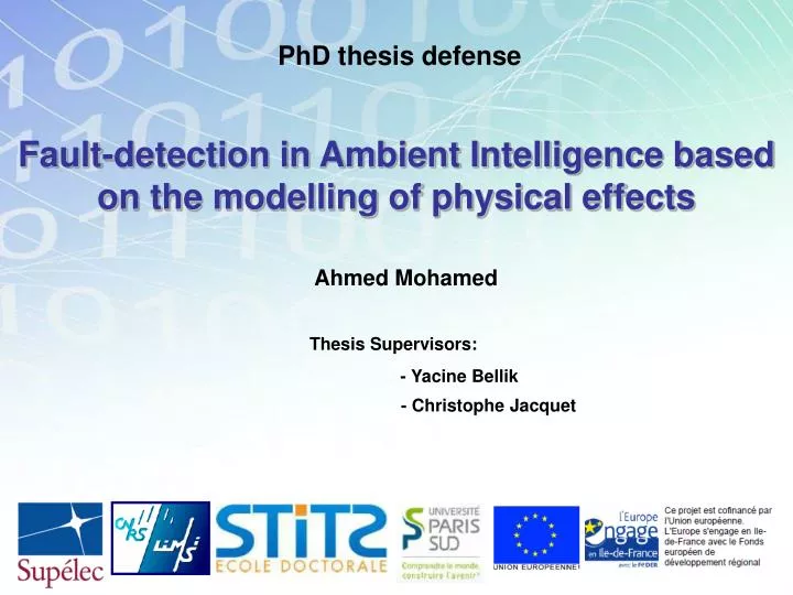
PhD thesis defense. Fault-detection in Ambient Intelligence based on the modelling of physical effects. Ahmed Mohamed. Thesis Supervisors:. - Yacine Bellik - Christophe Jacquet. Outline. Introduction State of the art & motivation Our contribution The concept of “Effect”

E N D
PhD thesis defense Fault-detection in Ambient Intelligence based on the modelling of physical effects Ahmed Mohamed Thesis Supervisors: • - Yacine Bellik • - Christophe Jacquet
Outline • Introduction • State of the art & motivation • Our contribution • The concept of “Effect” • AmILoop: Fault Detection and Diagnosis Framework • The Prediction Model • Fault Detection Example • Effect Modifier • Conclusion • Perspectives
Outline • Introduction • State of the art & motivation • Our contribution • The concept of “Effect” • AmILoop: Fault Detection and Diagnosis Framework • The Prediction Model • Fault Detection Example • Effect Modifier • Conclusion • Perspectives
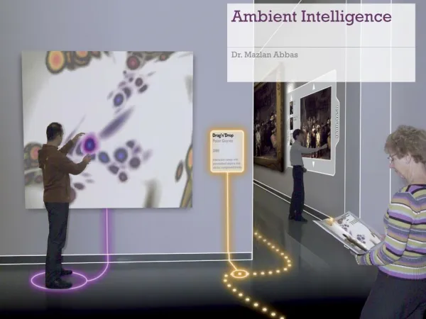
IntroductionAmI Context • Ambient Intelligence • “The most profound technologies are those that disappear. They weave themselves into the fabric of everyday life until they are indistinguishable from it.”- [Weiser. 1991] • Ambient environments are smart environments that are sensitive and responsive to the presence of people in a non intrusive manner • Goal • Users’ comfort: satisfy users’ preferences and needs • Execute tasks or assist users in their tasks 1
IntroductionAmI Context • AmI Hardware Components • Sensors • Actuators • AmI Operation • Activate some Actuators, based on: • Data provided by some Sensors • User commands or actions • AmI Tasks User Tasks (actions) Identification Assistance User Interaction Tasks System Tasks Supervision / Monitoring Tasks Categories Studied Problems 2
IntroductionAmI Context • Application Domains of AmI systems • Home Comfort • Smart Homes / Offices. ex: ISpace [Callagan et al. 2006] • Transport • Smart cars, Collaborative GPS, Smart Public Transport • Commerce / Industries • Smart Exhibitions, Smart Industrial Plants and factories • Assistance for physically impaired / elderly • Smart Hospitals, MPC, Home Healthcare Monitoring and Assistance There is a Danger in case of Failures to continue to rely on “non intrusive” malfunctioning systems!! ISpace Smart Home Mobile Point of Care 3
Outline • Introduction • State of the art & motivation • Our contribution • The concept of “Effect” • AmILoop: Fault Detection and Diagnosis Framework • The Prediction Model • Fault Detection Example • Effect Modifier • Conclusion • Perspectives
State of the art • Definitions • A malfunctioning system is usually a result of a failing/faulty part. • In the field of diagnosis a “Fault” is a deviation of the actual system from the system model, causing it to fail to fulfill its goal(s). • Fault Detection Vs Fault Diagnosis [Gertler. 1998] • Fault Detection • Fault Isolation • Fault Identification Fault Diagnosis 4
State of the art • Definitions • A malfunctioning system is usually a result of a failing/faulty part. • In the field of diagnosis a “Fault” is a deviation of the actual system from the system model, causing it to fail to fulfill its goal(s). • Fault Detection Vs Fault Diagnosis [Gertler. 1998] • Fault Detection • Fault Isolation • Fault Identification Fault Diagnosis Ex: Car engine Sensors Detect the Fault 4
State of the art • Definitions • A malfunctioning system is usually a result of a failing/faulty part. • In the field of diagnosis a “Fault” is a deviation of the actual system from the system model, causing it to fail to fulfill its goal(s). • Fault Detection Vs Fault Diagnosis [Gertler. 1998] • Fault Detection • Fault Isolation • Fault Identification Fault Diagnosis Ex: Car engine Sensors Detect the Fault Fault is Diagnosed to be fixed 4
State of the art • Definitions • Model Based Fault Detection and Diagnosis Approach • To perform real-time Fault Detection, the system model and the actual system are to be compared at all time in order to monitor any deviation. Real Measurements Actual System Fault Detection & Diagnosis Command Input Model of The System Expected Measurements 5
State of the art • Definitions • Model Based Fault Detection and Diagnosis Approach Real Measurements Actual System Fault Detection & Diagnosis Command Input Model of The System Expected Measurements Workflow: Actual System System Model Modeling 6
State of the art • Definitions • Model Based Fault Detection and Diagnosis Approach Real Measurements Actual System Fault Detection & Diagnosis Command Input Model of The System Expected Measurements Workflow: Real Observations Actual System Observing System Model Predicted Observations Modeling Simulating 6
State of the art • Definitions • Model Based Fault Detection and Diagnosis Approach Real Measurements Actual System Fault Detection & Diagnosis Command Input Model of The System Expected Measurements Workflow: Real Observations Actual System Observing Comparing System Model Predicted Observations Modeling Simulating 6
State of the art • Definitions • Model Based Fault Detection and Diagnosis Approach Real Measurements Actual System Fault Detection & Diagnosis Command Input Model of The System Expected Measurements Workflow: Real Observations Actual System Observing Comparing Fault Detection System Model Predicted Observations Modeling Simulating 6
State of the art • Definitions • Model Based Fault Detection and Diagnosis Approach Real Measurements Actual System Fault Detection & Diagnosis Command Input Model of The System Expected Measurements Workflow: Real Observations Actual System Observing Analyzing Symptoms Comparing Fault Diagnosis Fault Detection System Model Predicted Observations Modeling Simulating 6
State of the art • Definitions • Model Based Fault Detection and Diagnosis Approach Real Measurements Actual System Fault Detection & Diagnosis Command Input Model of The System Expected Measurements Workflow: Real Observations Actual System Observing Analyzing Symptoms Comparing Correcting Fault Diagnosis Fault Detection System Model Predicted Observations Modeling Simulating 6
State of the art • Existing Work • Home based Healthcare Monitoring Systems Use spatio-temporal reasoning to analyze cameras feeds[Augusto et al. 2007] Assisting the health carers by anticipating problems, explaining directive, alerts, etc. • Context Aware AmI Systems (The Context Awareness middleware monitors the surroundings and reacts to the changes according to specific “adaptation rules”) • Equip the context awareness middleware with the capabilities to detect the firing of the wrong orders/actions. Definition of a formal finite-state model of adaptation rules [Sama et al. 2008] • Detecting adaptation faults by comparing the Model to the Actual System. 7
State of the art • Classical diagnosis problem Light Bulb +220V Turn_Light_On() OK Software Hardware Non Ambient System “Turn Light On” order is executed with success because the Hardware part successfully closed the circuit. 8
State of the art • Classical diagnosis problem Light Bulb +220V Turn_Light_On() OK Software Hardware Non Ambient System “Turn Light On” order is executed with success because the Hardware part successfully closed the circuit. 8
State of the art • Classical diagnosis problem Light Bulb Control loop Sensor +220V Turn_Light_On() OK Software Hardware Non ambient System The ad-hoc “control loop” solution. But, “ad-hoc” solution are not adapted to “open” Ambient Intelligent Systems 8
Motivation • Ambient diagnosis Sensors Light Bulbs +220V Turn_Light_On() OK Software Hardware Ambient System Need to discover the right sensors at run-time and build control loops opportunistically. 9
Motivation • Ambient diagnosis Sensors Light Bulbs +220V Turn_Light_On() OK Software Hardware Ambient System Need to discover the right sensors at run-time and build control loops opportunistically. 9
Motivation • Ambient diagnosis Sensors Light Bulbs +220V Turn_Light_On() OK Software Hardware Ambient System Need to discover the right sensors at run-time and build control loops opportunistically. 9
Motivation • Ambient diagnosis Sensors Light Bulbs +220V Turn_Light_On() OK Software Hardware Ambient System Need to discover the right sensors at run-time and build control loops opportunistically. 9
Motivation • Ambient diagnosis Sensors Light Bulbs +220V Turn_Light_On() OK Software Hardware Ambient System Need to discover the right sensors at run-time and build control loops opportunistically. 9
Motivation • Ambient diagnosis Sensors Light Bulbs +220V Turn_Light_On() OK Software Hardware Ambient System Need to discover the right sensors at run-time and build control loops opportunistically. 9
Motivation • Ambient diagnosis Sensors Light Bulbs +220V Turn_Light_On() OK Software Hardware Ambient System Need to discover the right sensors at run-time and build control loops opportunistically. 9
Motivation • Ambient diagnosis Sensors Light Bulbs +220V Turn_Light_On() OK Software Hardware Ambient System Need to discover the right sensors at run-time and build control loops opportunistically. 9
Motivation • Ambient diagnosis Sensors Light Bulbs +220V Turn_Light_On() OK Software Hardware Ambient System Need to discover the right sensors at run-time and build control loops opportunistically. 9
Outline • Introduction • State of the art & motivation • Our contribution • The concept of “Effect” • AmILoop: Fault Detection and Diagnosis Framework • The Prediction Model • Fault Detection Example • Effect Modifier • Conclusion • Perspectives Real Observations Actual System Observing Analyzing Symptoms Comparing Correcting Fault Diagnosis Fault Detection System Model Predicted Observations Modeling Simulating
Our contributionThe concept of “Effect” • Decoupling of actuators and sensors Perceive Act upon Ambient environment Challenge: Given that we have no pre-determined links between actuators and sensors We want to determine these links automatically at run-time 10
Our contributionThe concept of “Effect” • Decoupling of actuators and sensors Perceive Act upon Ambient environment Challenge: Given that we have no pre-determined links between actuators and sensors We want to determine these links automatically at run-time 10
Our contributionThe concept of “Effect” • Decoupling of actuators and sensors Perceive Act upon Ambient environment Challenge: Given that we have no pre-determined links between actuators and sensors We want to determine these links automatically at run-time 10
Our contributionThe concept of “Effect” • Decoupling of actuators and sensors Perceive Act upon Ambient environment Challenge: Given that we have no pre-determined links between actuators and sensors We want to determine these links automatically at run-time 10
Our contributionThe concept of “Effect” • Decoupling of actuators and sensors Perceive Act upon Ambient environment Challenge: Given that we have no pre-determined links between actuators and sensors We want to determine these links automatically at run-time 10
Our contributionThe concept of “Effect” • Decoupling of actuators and sensors Perceive Act upon Ambient environment Challenge: Given that we have no pre-determined links between actuators and sensors We want to determine these links automatically at run-time 10
Our contributionThe concept of “Effect” • Decoupling of actuators and sensors Perceive Act upon Ambient environment Challenge: Given that we have no pre-determined links between actuators and sensors We want to determine these links automatically at run-time 10
Our contributionThe concept of “Effect” • Decoupling of actuators and sensors Perceive Act upon Ambient environment Challenge: Given that we have no pre-determined links between actuators and sensors We want to determine these links automatically at run-time 10
Our contributionThe concept of “Effect” • Decoupling of actuators and sensors Perceive Act upon Ambient environment Challenge: Given that we have no pre-determined links between actuators and sensors We want to determine these links automatically at run-time 10
Our contributionThe concept of “Effect” • Decoupling of actuators and sensors Perceive Act upon Ambient environment Challenge: Given that we have no pre-determined links between actuators and sensors We want to determine these links automatically at run-time 10
Our contributionThe concept of “Effect” • Decoupling of actuators and sensors Detect Produce Physical phenomena (Effects) Ambient environment Solution: • Model the physical effects • Use them to deduce links between actuators and sensors • (+) Also use them to predict the values expected at the sensors 11
Our contributionThe concept of “Effect” • Decoupling of actuators and sensors Detect Produce Light Sensors Light Actuators Light Effect Heat Effect Heat Sensors Heat Actuators X Effect Physical phenomena (Effects) Ambient environment Solution: • Model the physical effects • Use them to deduce links between actuators and sensors • (+) Also use them to predict the values expected at the sensors 12
Outline • Introduction • State of the art & motivation • Our contribution • The concept of “Effect” • AmILoop: Fault Detection and Diagnosis Framework • The Prediction Model • Fault Detection Example • Effect Modifier • Conclusion • Perspectives Real Observations Actual System Observing Analyzing Symptoms Comparing Correcting Fault Diagnosis Fault Detection System Model Predicted Observations Modeling Simulating
Our contributionThe FDD Framework • Modeling the Ambient Environment • The Models: (three levels of abstraction) Level 1: Abstract level for shared characteristics Level 2: Concrete level to define types of components Level 3: Instance level for individual devices Abstract Environment Model Static (design time) Concrete Environment Model Environment Instances Dynamic (run-time) 13
has property has property Actuator Property Property Sensor produces detects input input Effect input output Effect Property Law Set Measurable Property Our contributionThe FDD Framework • Modeling the Ambient Environment • The Models: (three levels of abstraction) Level 1: Abstract level for shared characteristics Level 2: Concrete level to define types of components Level 3: Instance level for individual devices Abstract Environment Model Concrete Environment Model Environment Instances 13
Our contributionThe FDD Framework • Modeling the Ambient Environment • The Models: (three levels of abstraction) Level 1: Abstract level for shared characteristics Level 2: Concrete level to define types of components Level 3: Instance level for individual devices Abstract Environment Model Concrete Environment Model Environment Instances 14
has property has property Actuator Property Property Sensor produces detects input input Effect input output Effect Property Law Set Measurable Property Our contributionThe FDD Framework • Modeling the Ambient Environment • From the Abstract Model to the Concrete Model Incandescent Light Bulbs Compact Fluorescent Light Bulbs Photo Resistor Light Sensors 15
has property has property Actuator Property Property Sensor produces detects input input Effect input output Effect Property Law Set Measurable Property Our contributionThe FDD Framework • Modeling the Ambient Environment • From the Abstract Model to the Concrete Model Incandescent Light Bulbs Compact Fluorescent Light Bulbs Photo Resistor Light Sensors has property has property Incandescent Bulb Position Position Photo Resistor CFL Bulb produces detects input input Light Effect input output Luminous Flux Light Law Set Ambient Light Intensity 15
Our contributionThe FDD Framework • Modeling of Law Sets has property has property Incandescent Bulb Position Position Photo Resistor CFL Bulb produces detects input input Light Effect input output Luminous Flux Light Law Set Ambient Light Intensity Different levels of detail 3D Light Law Set Most Detailed 2D Light Law Set On/Off Light Law Set Least Detailed 16