Download
1 / 24
240 likes | 383 Views
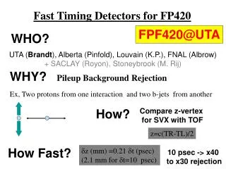
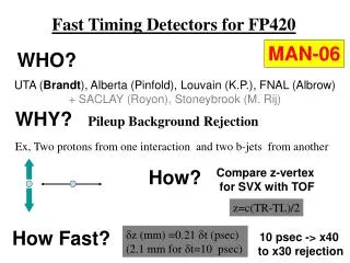
Fast Timing Detectors for FP420. WHO?. UTA ( Brandt ), Alberta (Pinfold), Louvain (K.P.), FNAL (Albrow) +LLNL (Gronberg). WHY?. Pileup Background Rejection. Ex: 3 interactions, one with hard scatter, and two with diffractive protons. How?. Compare z-vertex for SVX with TOF. z=c(TR-TL)/2.

E N D
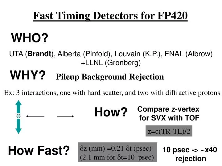
Fast Timing Detectors for FP420 WHO? UTA (Brandt), Alberta (Pinfold), Louvain (K.P.), FNAL (Albrow) +LLNL (Gronberg) WHY? Pileup Background Rejection Ex: 3 interactions, one with hard scatter, and two with diffractive protons How? Compare z-vertex for SVX with TOF z=c(TR-TL)/2 How Fast? z (mm) =0.21 t (psec) (2.1 mm for t=10 psec) 10 psec -> ~x40 rejection
The Detectors : 1) GASTOF (Louvain) http://www.fynu.ucl.ac.be/themes/he/ggamma/Cherenkov/ Presents little material to beam, extremely fast
The Detectors : 2) QUARTIC proton V2 Segmented, provides multiple measurements
Baseline Plan 2 QUARTICs Lots of silicon 1 GASTOF
T958 • Fermilab Test beam experiment to study fast timing counters for FP420 (Brandt spokesman) • Used prototype/preprototype detector with NIM/CAMAC to test concept in Fall 2006, Mar 2007 • Next run planned July 11-18 2007 Time resolution for the full detector system: 1. Intrinsec detector time resolution 2. Jitter in PMT's 3. Electronics (AMP/CFD/TDC)
First TB Initial Results G1-G2 For QUARTIC bar 110 psec Efficiency 50-60% For events with a few bars on see anticipated √N dependence <70 psec/Gastof (2500V) >90% efficiency
Upgrade for T958 Phase II March 7-20 • New detector prototypes, electronics, • Improved DAQ, alignment, analysis, tracking • Scope Data 10:00->12:30Fast Timing (UTA Workshop) 10:00 Fast Timing Test Beam Overview (20') Andrew 10:20 Scope Analysis (20') Tomek Pierzchala 10:40 Test Beam Analysis Plans (20') Pedro Duarte 11:00 Quartic Geant Simulation (20') Yushu Yao 11:20 Ray Tracing MC (20') Joaquin Noyola 11:40 Reference Timing (30') Mike http://indico.cern.ch/conferenceDisplay.py?confId=14046
T958 Electronics Phase I: Amplifier : Hamamatsu Ortec Phillips Burle 8x8 MCP-PMT 25 um pore Constant Fraction Discriminator Ortec 934 (9307) TDC (Phillips 7186) SMA SMA Lemo 10 um Burle or 6 um Hamamatsu HPTDC Phase II: Custom CFD (Louvain) Phase III: New 10 um Burle? LCFD V2, Amp+CFD board (Alberta)
TB Phase II Analysis • Pedro Duarte data analysis of CAMAC data • (TDC tracking) leads to understanding of coherent noise, tracking, efficiency, cross talk. • II) Tomek Pierzchala scope data analysis gives • data base of pulses, allows separation of detector/tube response from electronics. • Focus on scope analysis for this talk.
Scope (Tektronix DPO70404) Analysis Waveform2 sample 755 events: Trigger Ch3xCh1CH1 QBE > Ortec9306CH2 G01 > HamamatsuCH3 G02 > ZX60CH4 QBD > 18dB > Phillips2
Using Scope Signals What time To use?
Scope Analysis (G1-G2) (t)=45 ps (t)=35 ps CFD algo simulated Threshhold discriminaton
Scope Analysis: Detector Resolution • time difference using LCFD • 23 GASTOFs 35±1ps • 14 QUARTICs 63±2ps • 12 74±3ps • 13 69±3ps • 24 64±3ps • 50±3ps • Overconstrained setup gives G1 = 42 ps G2=24 Q1=59 Q4=40
Scope Analysis: LCFD Resolution Ch4=LCFD output of same bar as ch1 raw pulse Difference gives LCFD resolution (t)=40 ps Noise? Saturation
Concerns Efficiency: From tracking+scope Q about 60%, G2 from tracking 10-30% (CFD threshhold?) Correlation/cross talk: Track not in row of bar but bar on Background—not tested Rad Hardness of electronics Readout
Extrapolating Current QUARTIC/PMT resolution ~60ps Louvain CFD ~40 ps, software optimization implies might reduce this to 20 ps, combined with TDC resolution of 20 ps gives 66 ps/bar 60% efficiency implies 10 measurements instead of 16 with two QUARTICs gives 21 ps QUARTICs only resolution GASTOF/PMT is 24 ps, combined with a single photon counter with <10 ps resolution would give 25 ps, which implies an overall system resolution of 15-20 ps And rejection factor ~30
Q3 Parallel tube to lower background, shorter light guide to increase light
Short kink Long kink aka Dogleg <#p.e.>=5.5 <#p.e.>=3.5
6 4 2.5 L.K. S.K Q2-4
TB III: July 11-18 • LCFD v2, better algo dual output for HPTDC tests • Alberta amp/CFD board • Scope analysis, more systematic • Q2 vs Q3 • GASTOF 2 efficiency • Q correlations • Compare Phillips 7186 TDC and HPTDC
GOOD NEWS! • DOE ADR awarded A.B. $75k includes money for fast scope, CAEN HPTDC, electronics, travel to CERN testbeam, etc. • My sabbatical was approved by UTA, I plan to be at CERN Jan-Aug 2008
EIG1000D with PIL063SM (fiber coupler and fiber) • PiLas Digital Control Unit (EIG1000D) • Optical Heads (PILxxx) for 375 nm – 1550 nm) • Laser stand & irradiations • We resume June 22nd irradiations and tests with picosecond laser (PiLas) using blue laser head PIL040 - 408 nm, 32 ps pulse FWHM and < 3 ps jitter! Before and after irradiation series of laser pulses measured by Hamamatsu MCP-PMTs will be taken with 3 GHz LeCroy. We will scan Hamamatsu responses as a function of HV, pulse rate and number of photons per pulse. In next step, front-end electronics will be irradiated.
Optical box, with possibility of varying light attenuation in wide range Laser head Hamamtsu MCP-PMT