Download
1 / 35
350 likes | 360 Views
Lecture 2.6. Module 2. AVIATION TELECOMMUNICATION SYSTEMS Topic 2.6. HF Aviation Communication Systems.

E N D
Lecture 2.6.Module 2. AVIATION TELECOMMUNICATION SYSTEMSTopic 2.6. HF Aviation Communication Systems
Complex Propagation: Refraction, Absorption, Non-LOS PropagationDiscussion has so far been mainly concentrated on how radio waves propagate in free space with LOS conditions. This describes the majority case for aviation and most situations can be approximated to this.Occasionally, however, an aircraft will not have LOS to the nearest ground node. This is usually the case on a long approach, or approach in mountainous terrain or when the station is over the horizon. At such lower altitudes other propagation mechanisms can come into effect, such as reflection; refraction; ground wave/sky wave.
Refraction2.6.1.1 Layer RefractionThe k factor starts to introduce the concept of non-straight-line radio beams. This is essentially incremental refraction occurring at every point along the beam. Of course, in the limit, the phenomenon of total internal refraction or ‘ducting’(распространение по атмосферному волноводу) occurs and a radio beam can extend well beyond its natural horizon limits.
2.6.1.2 Obstacle RefractionA second type of refraction that occurs is that when the radio wave (showing its wave physics properties) is blocked by either a smooth obstacle that encroaches into its path or a knife-edge obstacle encroaching into its path. An attenuation of the beam occurs, which is a function ofthe Fresnel physics.
2.6.3 Non-LOS PropagationThere are a number of other mechanisms for which propagation can happen in non-direct LOS. These are via ground wave propagation (which tends to be more significant at low or very low frequencies, in kilohertz or less), reflection and refraction (which are both related and similar), which is prevalent in the HF, VHF and UHF bands.
2.6.3.1 Propagation – Ground WaveThis is when radio waves follow the curvature of the earth. This is particularly the case forlow frequencies and very low frequencies in the kilohertz region. Ground waves that followthe earth must be vertically polarized. The attenuation is a function of frequency and is lower at lower frequency.Generally ground wave propagation is not appropriate for aeronautical purposes, either infrequency (the aeronautical bands are too high in frequency) or application.
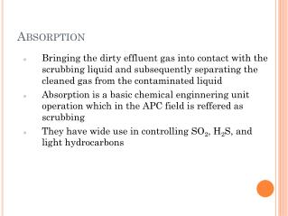
2.6.3.2 Reflection and MultipathHF, VHF, UHF and microwave frequencies lend themselves easily to reflection, refraction andmultipath. This is when by the law of physics, a ray is incident to a ‘reflective surface’ (and this can be, for example, still water, land, metal or a highly conductive surface). In undergoing a reflection, usually some losses are incurred but these can be small, in which case a reflected ray can be comparable with a direct ray in terms of incident power . From a practical perspective, this is the reason why these frequencies are often chosen for radar systems, which exploit this property.
For mobile communications, in some cases, this can be a favourable property, extending range and saturating coverage for certain systems (i.e. cellular mobiles) in a cluttered urbanenvironment where frequencies of 400 and 800MHz are well known for their good properties of bouncing off walls and propagating through windows and tunnels.Also for aviation the property can be useful, particularly at HF where relatively low-loss reflections can be used to provide long-range radio. However, in other aeronautical applications, particularly between low-altitude transceivers, usually it can also lead to severe attenuations even when direct LOS exists and is a very undesirable phenomenon.
2.6.3.2.1 The Two-Ray ModelConsider an instance where two signals (one usually direct and one indirect) from the same source arrive at a receiver. Constructive or destructive fading can take place, resulting in either good or bad signal reception (Figure 2.19).This phenomenon is called multipath and becomes very significant for marginal LOS cases or radio communications close to the earth’s surface, particularly over water or in metallic cluttered environments such as around airports.
When multipath occurs and the delay period is less than a data period between two symbolstates in the digital environment, intersymbol interference will occur. Fig. describes example transmitted and received data stream in a multipath environment.
This can be seen when observing a data stream at the intermediate frequency (IF) level through an ‘eye diagram’. The eye will close as a function of how much reflected signal is arriving at the receiver and the intersymbol interference builds. Figure 2.21 shows how an eye diagram can be obtained.
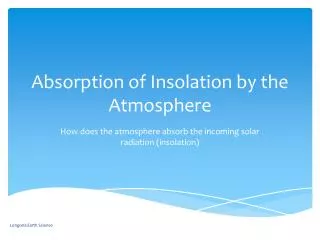
Propagation – Sky WaveSky wave propagation is an extension of the reflection theme. The waves that rely on the refractive properties of the ionosphere to propagate long distances are considered as sky waves. (In the limit, a refraction becomes a reflection; and hence the relationship to reflections.)This phenomenon is very frequent below 30 MHz. These properties are useful in that long-range communications can be provided well over the horizon. The HF band (3–30 MHz) is well suited for this and aviation and other radio users exploit this band for this very purpose.
Conversely the reflective properties of the ionosphere can occur into the low VHF band (above 30 MHz) and even beyond for a low proportion of time into the aeronautical communications band (currently 118–137 MHz). This is usually more of a problem where coverage can overreach past the horizon into an adjacent area sometimes up to 1000 km away using the samefrequency for a different application of airspace and consequently causing interference. HF traditionally is considered to extend from 3 to 30 MHz. The aeronautical HF band, however, is considered to extend a little before this to start at 2MHz and run up to 22 MHz. In the early days of radio, HF was a favorite band because the propagation properties are such that under certain conditions the wave can totally internally reflect or ‘skip’ its way right around the earth. In addition, the antenna properties are very efficient and finally, the transmitter/receiver was easily designed and economic. Today, this still holds true.
The IonosphereThe ionosphere extends nominally from 60 to 400 km above the earth’s surface. It is so called as the particles in this region are easily ionized, giving it special electrical properties. Under certain conditions the HF radio waves will refract and in the limit totally internally reflect or ‘duct’ (Figure 2.23).
ITU recommendation P.533-7 –‘HF Propagation Prediction Method’. It provides a theoretical method to calculate which frequencies are most suitable at which times. Maximum Usable Frequency. This is a median value statistically. The chances at the time of validity of an HF channel frequency being ‘open’ above this value are 50 %.Highest Possible Frequency. This is the HF, above which statistically there is only a 10% chance of the frequency being open.Optimum Working Frequency. This is the highest HF that gives a 85% likelihood of thechannel being open.
Practical Measurements – Ionosphere Sounding. This is a technique frequently used in practice to gauge the current ionosphere conditions and to be able to predict propagation. In its simplest form, consider sending a multifrequency signal straight up perpendicularly to earth’s surface and measure which frequency components are returned.A number of services send out ‘squitters’ or multifrequency components like this in their transmissions, and receivers can look at what they receive and analyze, and from this evaluatewhat the current propagation conditions are and which frequencies are best to use at that moment in time. In reality, this practical approach is found to be a more powerful method than the theory.
High-Frequency RadioThe very first aeronautical frequencies used for communications were actually HF. At the time this was for two reasons. Firstly the equipment was easy to make, with reasonably high-power amplifiers, and secondly the antenna systems are highly efficient so that most of the power being launched goes into the radio beam.The HF band lends itself to extensive range propagation with a low loss of reflection possible from the ionosphere, enabling various ‘modes’ to propagate thousands of kilometers and in some cases right the way around the world. This can be a blessing when in remote parts of the world or in areas of poor VHF coverage, but it can also equally be a hindrance in that unwanted radio transmissions can equally propagate a long way. The overall effect can be a build-up or aggregation of unwanted signals, which looks like interference to the HF receiver and an apparent lift in the noise floor. In fact with HF this is generally the case.
Also the availability of radio channels in the HF band is a function of which channels are ‘open’ and ‘closed’ at the time. This is ultimately dependent on time of day or night, sunspot activity, solar flares (which are to a degree random) and range.As a consequence of these two aspects, aviation has been awarded spectrum allocations right across the HF band between 2.8 and 30.0MHz to ensure a number of channels are open at any one time.
Allocation and AllotmentThis allotment plan was established at WRC 1978 and is commonly known as Appendix 27 to the radio regulations. The allocation has not changed substantively since then. There is increasing pressure on the services in the HF band to be used more efficiently and to minimize spurious intrusion into adjacent channels.To this end it was decided that after 1981, the use of the inefficient double-side band (DSB-AM) modulation would be phased out in favour of single-side band (SSB) modulation (conventionally the upper side band is used). This would immediately yield a double increase in channel capacity of the band as a whole. In 1995, the structure of the HF band was further redefined under ITU as Appendix S.27 to the radio regulations.
TransmitterThe transmitter is synthesized using Carson’s loop process or by direct filtering out of the lower side band and carrier. In general, for voice modulation the voice is band limited between 300 and 2700 Hz. The transmitters are tunable in 1-kHz steps, which is in keeping with the ITU band plan allotment defined for aeronautical HF in Appendix S.27.The RF emission has a given characteristic as a function of the pre-filtering, carrier filteringand post- (RF-) filtering. This is to ensure compatibility with co-channel and adjacent channelemissions. The emission masks have given characteristics; for the AM(R)S service in HF thesecan be J3E, J7B and J9B (for selective calling, sometimes called SELCAL, it is H2B).For aircraft stations the allowable peak envelope power is generally up to 26dBW (400Wmax into antenna Tx line) (in some special cases up to 600W is allowed), and for groundstations, emissions Tx power up to 37.78dBW (6 kW); these limits come from the ICAOSARPs and ITU Appendix S.27.The frequency accuracy of airborne transmitters must be within 20 Hz of allocation; forground transmitters this is even more stringent and must be within 10 Hz of allocation (3.33x 10⁻⁵ %). This fairly tight specification is to safeguard out-of-band emissions into adjacentchannels. With today’s technology, this is easy to meet.
ReceiverThe receiver deploys a Carson’s loop receiver. The frequency stability of the receiver function from the ICAOSARPs must be less than 45 Hz. On the surface, this may seem inconsistent with the transmitter specification; however, the capture effect will ensure the HF receiver is locked onto the received signal. A typical sensitivity of the receiver is quoted as 2 μV/m for 6 dB S/(S + N) for the J3E-type emission. System ConfigurationThe aeronautical HF system channels can be operated in two different ways. Open channels shared between multiple users in broadcast mode enable a channel to be used in simplex.Selective calling channels are used bidirectionally in half-duplex mode between an aeronautical station and a ground station. The two parties identify each other via a unique station number (much like a telephone DTMF Code).
Selective Calling (SELCAL)To permit the SELCAL of individual aircraft over radiotelephone channels linking the ground station (or other aircraft) with the aircraft, the individual stations must be allocated a calling code. There are 16 300 codes available in the world. SELCAL is accomplished by the coder of the ground transmitter sending a simple group of coded tone pulses to the aircraft receiver and decoder. It uses multifrequency dual tonesexactly like the more modern telephone exchanges.When using HF, there can be a small delay compared to the perceived ‘instantaneous’ nature of VHF. This is because the propagation time delay is a function of distance. So for a long path (say 9000 km), this can get up to as much as 30 ms. This is just noticeable but not as severe assatellite systems.
Channel AvailabilityICAO has defined the world surface as split up into 14 separate zones or geographical areas that it calls ‘major world air route areas’ (MWARAs). Such areas are, for example, the NorthAtlantic, the Caribbean, the north Pacific, Southeast Asia, South America, Indian Ocean. (The detailed delineation can be found in ICAO Annex 10). Each one of these has its own HF groundstation(s).The ground stations will be allotted a number of frequency channels. These are a sub-band of the total aviation frequency pool. They are chosen to minimize interference into adjacentMWARAs and to give each MWARA a broad range of available channels across the total 27MHz so that at any given time, some or most of the channels are open for reliable HF communications.