Download
1 / 33
330 likes | 474 Views
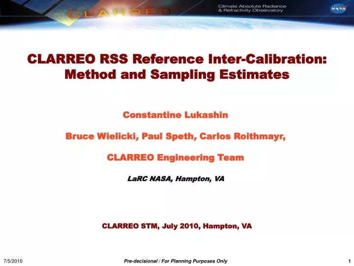
CLARREO RSS Reference Inter-Calibration: Method and Sampling Estimates . Constantine Lukashin Bruce Wielicki , Paul Speth , Carlos Roithmayr , CLARREO Engineering Team LaRC NASA, Hampton, VA. CLARREO STM, July 2010, Hampton, VA. Presentation Outline.

E N D
CLARREO RSS Reference Inter-Calibration: Method and Sampling Estimates Constantine Lukashin Bruce Wielicki, Paul Speth, Carlos Roithmayr, CLARREO Engineering Team LaRC NASA, Hampton, VA CLARREO STM, July 2010, Hampton, VA
Presentation Outline • Reference Inter-calibration strategy & method • CLARREO RS reference inter-calibration goals: • - inter-calibration of broadband sensor (JPSS/CERES) • - inter-calibration of an imager (JPSS/VIIRS) • DAC-5 Observatory Configuration and Orbital Simulations of orbit crossing with JPSS & MetOp • Reference Inter-calibration sampling estimates: • - JPSS/VIIRS (cross-track) • - JPSS/CERES (cross-track) • RI of VIIRS Sensitivity to Polarization: uncertainty • CLARREO RS instrument noise contribution to RI • Recommendation for mission requirements
Acknowledgment for Data (1)Used in Reference Inter-Calibration Studies • SCIAMACHY Level-1 spectral radiance data obtained from ESA. • - Used to simulate CLARREO spectral radiances, CERES broadband and • VIIRS narrowband radiances, 250 – 1750 nm wavelength range, seasonal months 2003 – 2007. • - Used by MODIS team to demonstrate sensitivity to detection of MODIS • band SRF Central Wavelength shift (to be published soon). • - Used by CERES TISA group for inter-calibration of Geo S/C. • CERES/MODIS/Terra SSF data is used to provide scene description for SCIAMACHY field-of-view (5 locations per FOV). • POLDER-3/PARASOL Level-1data obtained from CNES, and Level-2 Clouds & Radiance Budget data from ICARE, France. • - Used to simulate distributions of observed polarization for inter-calibration sampling, development of empirical polarization distribution models.
Acknowledgment for Data (2)Used in Reference Inter-Calibration Studies • - Used to derive requirement for CLARREO RS sensitivity to polarization. • CERES/MODIS/Aqua SSF data used to simulate scene type distributions within reference inter-calibration sampling of CLARREO RSS and JPSS sensors.
CLARREO RSS Inter-Calibration Strategy • 1) CLARREO RSS will create benchmark climate data records • using two complementary approaches: • - Benchmark using only CLARREO RSS data: spectral • optimal fingerprinting (see ZhonghaiJin’s presentation) • - Benchmark using CLARREO for reference inter- • calibration of operational sensors • 2) RI Method: Comparison of sensor measurementswith high • accuracy standard in orbit (CLARREO RSS). • 3) CLARREO RSS measurements to be used as reference for: • -Sensoroffset and gain • - Spectral response function degradation or shift • - Sensitivity to Polarization • - Non-linearity • 4) CLARREO RSS RI goal: Error contribution ≤ 0.3% (k=2) • over autocorrelation time period of18 months (Leroy et al., 2008) • RI Error is considered to be random (D. Tobin’s presentation)
CLARREO RSS Inter-Calibration Goals • Goals are set at noise level ≈ 1% (sources: instrument + data matching ) • RI error ≤ 0.3% (k=2) over auto-correlation time period = 18 months 1) CLARREO Inter-Calibration Goal: CERES 2) CLARREO Inter-Calibration Goal: VIIRS
Example: CERES SRF Degradation Testclear ocean (N = 1800) and marine clouds scenes (N = 7000) • CERES RSR Degradation: • α = 9.8155 (D=0.999 @ λ=0.7 μm) • Plots: • Top: CERES – CLARREO difference versus CLARREO signals (%). • Middle: CERES – CLARREO difference versus CLARREO signals (%) with 1% matching noise. • Bottom: Relative difference between • CLARREO and CERES signals with noise reduced by averaging. * CLRO: Offset error (2σ) = 0.21% * MCLD: Offset error (2σ) = 0.10%
CLARREO Sampling: Error Scaling Assuming 1% space/time/angles data matching (Wielicki et al., IGARSS 2008), only linear case differences with CLARREO (offset and gain only), the reference inter-calibration error should be reduced as sqrt(N) as number of samples decreases. From simulation using SCIAMACHY spectral data (clear-sky ocean case)
CLARREO Sampling: Fractions of Scene Types • Based on near-nadir CERES/MODIS/Aqua data (VZA < 10o, 20 km FOV). • SZA < 75o. • Distribution in latitude similar to CLARREO-JPSS inter-calibration • sampling (Studies by Speth & Roithmayr) CLEAR SKY: Cloud fraction < 0.1%.
Distribution of DOP (RI global sampling) • PARASOL Level-1 data: 12 days of 2006, accuracy 2-3%. • (1 day per month, “cross-track” sampling) • Distribution in latitude similar to CLARREO-JPSS RI sampling. • SZA < 75o. • DOP = linear degree of polarization
CLARREO RS RI Required Sampling: Monthly • CERES RI: All collected data together. • For VIIRS RI: Factor 2 for DOP ≤ 0.05 (670 nm), factor 7 for VZA, and • factor 2 for HAM sides. Total = factor 28.
CLARREO RS RI Required Sampling: Seasonally • CERES RI: Factor of 30 for clear-sky ocean scene (3% of global sampling). • For VIIRS RI: factor 10 for DOP = 0.2 – 0.4 (670 nm), 7 for VZA, 9 for χ, • and factor of 2 for HAM side. Total = factor of 1,260.
DAC-4 CLARREO Observatory Configuration: Both Spectrometers + GNSS-RO (CLARREO Engineering Team, January 2010) Double-axis (2D) gimbal to provide angular data matching in both yaw and roll angles. RSS located on nadir deck. No bus maneuver required for CLARREO RSS RI operations.
DAC-5 CLARREO Observatory Configuration: RSS + GNSS-RO (CLARREO Engineering Team, Current Baseline) Single axis gimbal provides for “Roll” or cross-track pointing DAC-5 concepts require “yaw” or +Z rotation by the S/C bus. • Angular matching: • “Yaw” maneuver allows to • match azimuth angle. • Gimbal “Roll” allows to • match scan/VZA angle Nadir (+Z) OFF Nadir +55o OFF Nadir -55o
Orbital Simulations (Carlos Roithmayr & Paul Speth) DAC-5 CLARREO RSS RI Operations option: 1) S/C Yaw (azimuth angle) q1 match = constant (matching within 0.5o) 2) Continuous Gimbal Roll (scan angle) q2 match = q2(t) • Goal: • Time/space/angle matching to obtain ensemble of • samples with data matching noise ≤ 1% • Wielicki et al., IGARSS 2008 • Matching requirements: • 5 min within JPSS passing • Viewing Zenith Angle matchwithin1.4°, SZA < 75o • At least 10 km effective width of CLARREO swath CLARREO-1 RS boresight locations matching JPSS cross-track data over one year time period
Geometry of RI Event Diagrams for DAC-5 Operation Option Top view Projection in JPSS cross-track plane Note: All matched data (red parallelogram) is aligned with JPSS cross-track direction
Orbital Simulations: CLARREO-1 (2017) and 2 (2020) with JPSS (Carlos Roithmayr & Paul Speth) Inter-Calibration Time per Day: CLARREO RSS is matched to JPSS in 833 km sun synch orbit. CLARREO-1 Mission START: Autumn Equinox, P90 orbit, Ω = 0o (orbital plane parallel to Earth-Sun direction) *Ω = right ascension of the ascending node, or RAAN CLARREO-2 Mission START: Autumn Equinox, P90 orbit, Ω = 90o (orbital plane perpendicular to Earth-Sun direction). CLARREO Orbits should be optimized: Study is in progress…
Orbital Simulations: CLARREO-1 (2017) with JPSS and METOP (Carlos Roithmayr & Paul Speth) Inter-Calibration Time per Day: CLARREO RSS is matched to JPSS in 1:30 pm (top); and METOP in 9:30 a.m. sun synch orbit. Both SS target orbits are at 833 km altitude. CLARREO-1 Mission START: Autumn Equinox, P90 orbit, Ω = 0o (orbital plane parallel to Earth-Sun direction) RI Events on 2018.03.03: no overlap. Yaw Time = 30.8 + 2.1×|q1| - 0.01×|q1|2 Inter-Calibration Operation Schedule: Taking into account time for yaw maneuver 134 RI JPSS/METOP events overlap over one year time period (out of total 1,330 events). 7/5/2010 Pre-decisional / For Planning Purposes Only
Orbital Simulations: RI and Operation Time (Carlos Roithmayr & Paul Speth) CLARREO-1 Inter-Calibration time: Time of RI Event with all data matching restrictions (space/time/angles) DAC-5 CLARREO RSS Bus: Yaw Time = 30.8 + 2.1×|q1| - 0.01×|q1|2 CLARREO-1 Operation time: Inter-Calibration time + 2 Yaw Time intervals Schedule of this Operation Time for CLARREO-1 RI with JPSS and METOP is generated. • Examples of Scheduling Priorities: • - RI Time interval (minimum duration/number of samples); • - RI Time versus Operation time (efficiency); • - Tropics versus polar regions (clear-sky ocean scene), oversampling in high latitudes; • RI versus Solar/Lunar calibration operations (potential scheduling conflict); • Minimization of RI impact on the benchmark (D. Doelling Group).
Sampling Estimate and Constrains • Sampling for AVHRR/VIIRS is nadir equivalent 10×10 km area in angular space, • 1o CLARREO elevation angle. To estimate number of samples with independent • spatial noise 1 km shift (0.1o in elevation angle ) is required from one sample to • the next in both spatial directions (along CLARREO frame and along ground • track). With CLARREO spatial resolution of 0.5×0.5 km the 1 km shift ensures • that only 2 boundary pixels are common. • - This approach of forming a CLARREO/VIIRS RI sample does not allow inter- • calibration on detector-by-detector basis. Relative calibration (flat-fielding) • is required using VIIRS data alone. • CERES IR sampling is estimated taking into account CERES FOV size of 25 km • at nadir (from JPSS orbit, 2.5o in CLARREO elevation angle), and data acquisition • rate 330/180 = 1.8 footprints per degree of scan angle every 3.3 seconds. • Constrains: • SZA < 75o (to ensure high SNR); • CLARREO effective swath > 10 km in VIIRS case, and > 25 km in CERES case. • VZA difference < 1.4o, SZA and RAZ are matched within 1o.
Sampling Summary for CLARREO-1/JPSS Monthly (top) and seasonal (bottom) sampling withVIIRS andCERES Red Errors: Required number of samples for RI monthly error contribution 1.2% (k=2) Red Lines: Required number of samples for RI seasonal error contribution 0.7% (k=2) WARNING: The required number of RI samples is derived under assumption of uniform sampling distributionin relevant parameters to VIIRS sensitivity to polarization: DOP and polarization angle.
Distribution of DOP, PARASOL Data, 2006.10.02 Average on 1o×1o grid, fractional units, “cross-track” mode λ =490 nm * RAZ < 90o is to the left of the ground track * RAZ > 90o is to the right of the ground track λ =670 nm λ =865 nm * For cross-track data tacking mode DOP distribution is has systematic dependence on viewing geometry.
Distributions of DOP and Polarization Angle PARASOL Data, 12 days 2006, simulated cross-track RI sampling - λ =490 nm - if (χ < 0) χmod = 180o + χ * Color scale = Relative sampling Forward Scatter Back Scatter
Possible RI of VIIRS on detector-by-detector basis, Diagram, Sampling plots, more studies - Angular matching within 1.4o VZA • Spatial matching: about • 300 pixels VIIRS and 400 CLARREO • (2 consecutive frames) • Study needed to estimate spatial • matching noise (using MODIS • 250 m resolution data) • CLARREO reading data rate could • beincreased (to reduce spatial • noise) Note: VIIRS scans cross-track with 16 detectors/band in a-track direction every 1.5 sec or every 11 km. 11 km swath is built by 16 detectors.
Sensitivity to Polarization • For a particular instrument design instrument response function • can depend on polarization of reflected light (DOP) and phase • angle of polarization. • Definitions (consistent with PARASOL definitions): • Ip2 = Q 2 + U 2 ( V 2 is small ); DOP = Ip/ I ; χ = tan -1(U/Q) / 2 • where Ip = polarized radiance; DOP = Degree of Linear Polarization; • χ = angle of polarization relative to view plane. • Sensitivity to polarization of instrument optics translates into dependence of its effective gain on DOP, and viewing geometry of instrument (χangle) • (MODIS Characterization, Sun and Xiong, 2007) • Lmes = (1 + DOP × mQU) Ltoa(from Menghua Wang’s VIIRS memo) • mQU = sqrt (mQ2 + mU2) (mQU is function of χ) • If DOP ≈ 1 and uncertainties of DOP and mQU are large, error contribution • from polarization can be compatible with the radiometric errors, even the mQU is relatively small.
CLARREO RI: VIIRS Sensitivity to Polarization • CLARREO RS Reference Inter-Calibration Approach: • 1. Gain correction from comparison of CLARREO high absolute accuracy radiances for samples • matched within defined state of polarization and viewing geometry. • CLARREO = SI-traceable calibration source in orbit. • 2. State of polarization is obtained by applying Polarization Distribution Models (PDM). • Estimated empirical PDM instantaneous error is about 10% (k=1). RT model errors ? Prototype PDM and its STD, PARASOL Data (12 days of 2006, 1 per month): A-Train Orbit Cross-Track Sampling (PARASOL 12 days of 2006):
CLARREO RI: VIIRS Sensitivity to Polarization • 3. Inter-calibration uncertainty. • Lclarreo = (1 + DOP × mQU) Lviirs • mQU = (Lclarreo/ Lviirs - 1) / DOP = (Gp – G0) / DOP = ΔG / DOP • σm/ mQU= sqrt [ (σΔG / ΔG)2 + (σDOP / DOP )2 ] • σΔG = sqrt [ (σGp )2 + (σG0 )2 ] • σDOP= PDM accuracy (not the inst. error which averages out) • Notes: • The uncertainty of mQU can be reduced by multiple inter-calibration in different DOP ranges • (linear case, factor sqrt(N), requires larger sampling to get high DOP. • For VIIRS mQU is function of of wavelength (band), detector, half angle mirror (HAM) • side, scan angle and χ:mQU( λ, Detector, HAM, scan angle,χ). • VIIRS has 16 detectors in 11 km along-track direction scanning within ± 56o at 40 rpm rate: • a scan every 1.5 seconds. For CLARREO RI method consistency between detectors is • required (flat-fielding or relative calibration, VIIRS instrument team)
CLARREO RS Instrument Noise Contribution • CLARREO RS instrument noise contribution when inter-calibrating with CERES: integration over broadband range, error summation. • SCIAMACHY data used for simulation (at 4 nm spectral resolution). • CLARREO RS instrument SNR, defined for reflectance 0.3 at solar zenith angle 75o (current requirement): • - SNR > 20 in 320 – 380 nm; • - SNR > 30 in 380 – 900 nm; • - SNR > 20 in 900 – 2300 nm; • SNR = 20 is used in simulation for entire range. • Estimated instrument noise at maximum level of spectral radiance, • 0.09 W/(m2 sr nm) at 470 nm wavelength. Estimated instrument noise for • singe spectral sample is 0.0045 W/(m2 sr nm). Assuming that instrument • noise is non-correlated the total noise for the broadband is 0.087 W/(m2sr). • Single CLARREO Pixel: For all-sky scenes relative error increases from • 0.5% (at SZA=25o) to about 2.5% (at SZA=85o). For clear-sky ocean scene • relative error increases from 0.8% (at SZA=25o) to about 3.0% (at SZA=85o). • CERES FOV (25 km at nadir): contains about 2,000 CLARREO pixels. • Averaging reduces instrument noise contribution factor 40.
Summary: recommendation for mission requirements • CLARREO RSS accuracy, spectral range and resolution, spatial resolution • are required to be a reference in orbit. • 2D angular data matching (azimuth and elevation) is required: • constant in azimuth and varying in elevation within matching tent. • For mission baseline all reference inter-calibration goals are feasible from sampling point of view. CLARREO RS instrument in polar 90o orbit provides adequate sampling monthly, seasonally and annually for inter-calibration of • cross-track sensors on JPSS/METOP. • Polarization Distribution Models are required for inter-calibration sensor • sensitivity to polarization, and its stand-alone operation. • A global all-sky set of models should be built for DOP and polarization angle χ . • Future Work: • - Account for detailed distributions in DOP and polarization angle; • - CLARREO RSS orbit optimization; • - Develop operation / scheduling model; • - PDM development (one year of PARASOL data + RT model + APS data); • - Quantitative study on RI sample geometry and spatial noise (MODIS data).
CLARREO RS spectrometer baseline: • Radiance measurements with accuracy 0.3%(2σ) for the time of the mission, uncertainty due to sensitivity to polarization included. • Wavelength range from 320 to 2300 nm. • Spectral sampling = 4 nm. • Spatial resolution 0.5×0.5 km (65% of signal). • Pointing ability (gimbal or S/C). • Polarization Distribution Models to provide polarization information (both DOP and χ). • CLARREO RS Inter-Calibration Event: • orbits crossing of CLARREO with sensor • to be calibrated that allows time/angle/ • space matching • CLARREO RS Swath: 100 km (nadir) • CLARREO/Solar Inter-Calibration Sample: • area of 10 km scale for reduction • of spatial matching noise to 1% level. • (Wielicki et al., IGARSS 2008) • CLARREO RS Pixel: • 0.5×0.5 km observed area (65% of signal). Study needed to quantify sampling Geometry (MODIS data 250 m resolution) 7/5/2010 Pre-decisional / For Planning Purposes Only 31
DAC5 Configuration: 1 Observatory in 90o orbit Estimated Monthly N samples for CERES and VIIRS: Average error over one year period is 0.%(k=2) for CERES and 0.%(k=2) for VIIRS.
Operation Option DAC5: 1 Observatory in 90o orbit Seasonal N samples for CERES: Seasonal N samples for VIIRS: