Download
1 / 9
90 likes | 211 Views
MICE Muon Decay Rejection July 21, 2004. Tom Roberts Illinois Institute of Technology. Background. For 220 MeV/c μ + , c = 1.4 km, so in the 14 meters from TOF1 to TOF2 approximately 1% of the μ + will decay; we need to reduce that rate considerably

E N D
MICE Muon Decay RejectionJuly 21, 2004 Tom Roberts Illinois Institute of Technology
Background • For 220 MeV/c μ+, c = 1.4 km, so in the 14 meters from TOF1 to TOF2 approximately 1% of the μ+ will decay; we need to reduce that rate considerably • All plots use the JUNE04 beamline design, the proposal cooling channel, and the new downstream PID detectors with iron shield • Method: • New g4beamline element: particlefilter – can force particles to decay (disabling the normal Decay process for the particles) • A particlefilter was placed at successive Z positions to force μ+ => e+ decays at known positions (Beware: lines connect the points, but are unreliable because apertures cause these functions to not really be continuous as the lines imply)
Geometrical Acceptance for mu+ Decays Trigger = TOF0 & TOF1 & TOF2 TOF0 Ckov1 TOF1 Abs1 Abs2 Abs3 TOF2
mu+ Rate as Function of Z Do not believe the line between points TOF0 Ckov1 TOF1 Abs1 Abs2 Abs3 TOF2
Relative Rate of mu+ => e+ Decays into TOF2 Trigger = TOF0 & TOF1 & TOF2 TOF0 Ckov1 TOF1 Abs1 Abs2 Abs3 TOF2
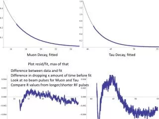
mu+ Decay Rejection using TOF2-TOF1 will be a Challenge Note all the positrons at larger times than most muons. Decays after Abs2 will of course have even larger times and be harder to distinguish from muons. Unfortunately, that is where the geometrical acceptance is largest.
The TOF2-TOF1 Challenge is not yet solved • In an ideal solenoid, Pz and Pperp determine the helical path through space, and Ptot/E determines the particle’s speed along that path. • This implies that to some approximation, TOF2-TOF1 for a muon ought to be a function only of Pz and Pperp measured in either tracker. • In practice, that’s not valid at all, and cuts on both Pz and Pperp do not yield a definite TOF2-TOF1 value for muons, nor do they permit a separation of decays via TOF2-TOF1.
For decays between the Trackers, we can cut on the correlation between Ptot in the two Trackers muons muon decays in Abs2 Empty absorbers – this will get worse with them full. (Resolutions of the Trackers are not included) Some/most decays within a Tracker might be rejected by Chisq of the track fit.
Conclusions (so far) • In the front region where the muon flux is very large, the geometrical acceptance for muon decays is very small. • But from Tracker1 to the end the geometrical acceptance for muon decays is significant. • Unlike the pion rejection in TOF1-TOF0, electron rejection in TOF2-TOF1 is not very good. • All pions enter the front of the timing region, electrons are generated by muon decays at an unknown place within the timing region. • The quads between TOF0 and TOF1 limit tracks to small angles (Δt<50ps); the solenoids between TOF1 and TOF2 permit large angles (Δt>5ns). • We may have to rely almost exclusively on the downstream Cherenkov2 and calorimeter for muon decay rejection. • More analysis is needed…