Download
1 / 110
1.1k likes | 1.19k Views
Leader Vision System Mounter. Mounting Coordinate Concepts. Plates are stepped across the cylinder, referenced from the web (cylinder) centerline in X direction. -X. +X. Plate X locations across cylinder. Cylinder X reference =0. Plate 1 X= -635mm. Plate 2 X= +635mm.

E N D
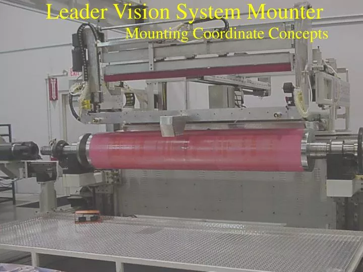
Leader Vision System Mounter Mounting Coordinate Concepts
Plates are stepped across the cylinder, referenced from the web (cylinder) centerline in X direction -X +X
Plate X locations across cylinder Cylinder X reference =0 Plate 1 X= -635mm Plate 2 X= +635mm NOTE THAT PLATE X MOUNTING LOCATION IS CENTER OF PLATE
Likewise, the Y location around the cylinder is referenced from the cylinder zero (scribe/keyway). Plate Y zero is the center of the plate and is the mounting point of the plate (X0,Y0). Plate Y Zero is center of the plate Cylinder Zero reference. Locations for plate mounting on the cylinder are by circumferential distance. 0 º 270 º 90 º 180 º
The Leader Mounter looks at the cylinder mounting locations in the Y as if the cylinder circumference were opened and laid out flat
The Leader Mounter looks at the cylinder mounting locations in the Y as if the cylinder circumference were opened and laid out flat
The Leader Mounter looks at the cylinder mounting locations in the Y as if the cylinder circumference were opened and laid out flat
The Leader Mounter looks at the cylinder mounting locations in the Y as if the cylinder circumference were opened and laid out flat
The Leader Mounter looks at the cylinder mounting locations in the Y as if the cylinder circumference were opened and laid out flat
The Leader Mounter looks at the cylinder mounting locations in the Y as if the cylinder circumference were opened and laid out flat
The Leader Mounter looks at the cylinder mounting locations as if the cylinder circumference were opened and laid out flat with center as X0,Y0. X0,Y0
The Leader Mounter looks at the cylinder mounting locations as if the cylinder circumference were opened and laid out flat with center as X0,Y0. X0,Y0 Y X
The Leader Mounter looks at the cylinder mounting locations as if the cylinder circumference were opened and laid out flat with center as X0,Y0. Plate mounting location on cylinder = X0,Y0 Plate X0,Y0 Y X
The Leader Mounter looks at the cylinder mounting locations as if the cylinder circumference were opened and laid out flat with center as X0,Y0. Plate mounting location on cylinder = X0,Y-254 Plate X0,Y0 Y X
The Leader Mounter looks at the cylinder mounting locations as if the cylinder circumference were opened and laid out flat with center as X0,Y0. Plate mounting location on cylinder = X0,Y+455 Plate X0,Y0 Y X
The Leader Mounter looks at the cylinder mounting locations as if the cylinder circumference were opened and laid out flat with center as X0,Y0. Plate mounting location on cylinder = X0,Y0 Plate X0,Y0 Y X
The Leader Mounter looks at the cylinder mounting locations as if the cylinder circumference were opened and laid out flat with center as X0,Y0. Plate mounting location on cylinder = X-250,Y0 Plate X0,Y0 Y X
The Leader Mounter looks at the cylinder mounting locations as if the cylinder circumference were opened and laid out flat with center as X0,Y0. Plate mounting location on cylinder = X+250,Y0 Plate X0,Y0 Y X
The Leader Mounter looks at the cylinder mounting locations as if the cylinder circumference were opened and laid out flat with center as X0,Y0. Plate mounting location on cylinder = X+250,Y-300 Plate X0,Y0 Y X
Two plates across and two plates around. Plate mounting location on cylinder = X-250,Y-300 Plate mounting location on cylinder = X-250,Y+300 Y Plate mounting location on cylinder = X+250,Y+300 Plate mounting location on cylinder = X+250,Y-300 X
We now know how the plate location on the cylinder is determined, but how is the plate center determined by the mounter? The center is known because the registers are referenced from the center of the plate. Thus the register X,Y location tell us the center of the plate. Plate center X0, Y0 X-280, Y0 X+280, Y0
The Leader mounter adds a new feature to mounting by permitting registers to be located anywhere on the printing plate. Also the register do not have to overlap between colors. Plate center X0, Y0 X-280, Y280 X+320, Y-300
This saves the customer consider plate material cost by making plates only large enough to contain the graphics. That is, all plates do not have to be the same size for the sake of overlaying registers. Conventional method Leader method Parrot food Parrot food
We have seen how the Leader mounter uses two register locations and the cylinder location for mounting. The plate length is also required for mounting to estimate Y0 of the plate. X0 is known since the plate center is placed at the approximate table center in the X direction.The following Leader mounting process explains this in more detail.
The unique design and operation of the Leader Vision System Mounter making it all possible.
A Snapshot of the Mounting Process Putting details aside for now, let us look at the basic concept of no hands alignment and mounting with the Leader Vision System Mounter
The operator places the printing plate reasonably straight at the approximate center of the table.
The operator verifies the approximate register location with a point and click of the mouse.
When ready, the telephoto camera moves to the first register
When ready, the telephoto camera moves to the first register
When ready, the telephoto camera moves to the first register
When ready, the telephoto camera moves to the first register
When ready, the telephoto camera moves to the first register
Operator verifies the center location with a point and click of the mouse
The same process is repeated for the second register. The Leader Vision System Mounter now knowing the exact location of the registers.
The printing plate is automatically rotated straight and the cylinder is automatically rotated to the proper mounting position.
The printing plate is automatically rotated straight and the cylinder is automatically rotated to the proper mounting position.
The printing plate is automatically rotated straight and the cylinder is automatically rotated to the proper mounting position.
The printing plate is automatically rotated straight and the cylinder is automatically rotated to the proper mounting position.
The printing plate is automatically rotated straight and the cylinder is automatically rotated to the proper mounting position.
The plate table automatically moves left or right to position plate in proper position across the web.
The plate table automatically moves left or right to position plate in proper position across the web.
The plate table automatically moves left or right to position plate in proper position across the web.
The plate table automatically moves left or right to position plate in proper position across the web.
The plate table automatically moves left or right to position plate in the proper position across the web.
The cylinder automatically raises to engage the sticky back (tape) to the back of the plate