Download
1 / 21
210 likes | 356 Views
FEE Commissioning. Hal Tompkins – Photon Beam Systems Deputy June 8, 2009. Beam Schedule. First beam into FEE late June/early July First beam into NEH late July First scheduled user run Sep-Dec. CD 4 goal of beam to FEH accomplished March, 2010. FEE Layout. Solid Attenuators.

E N D
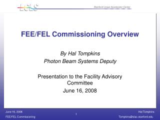
FEE Commissioning Hal Tompkins – Photon Beam Systems Deputy June 8, 2009
Beam Schedule • First beam into FEE late June/early July • First beam into NEH late July • First scheduled user run Sep-Dec. • CD 4 goal of beam to FEH accomplished March, 2010
FEELayout Solid Attenuators Gas Attenuator Thermal Sensor Beam Direction Slit Gas Detectors K-Mono 5 mm collimator Direct Imager (Scintillator) FEL Offset Mirror Systems
Phase 1 Commissioning • Commissioning time must be shared between electron and photon halves • Reliable lasing at all wavelengths has already been demonstrated • B4C testing is part of commissioning • Deposited power is greatest at 830 eV operation - estimated dose to B4C at ST1 is .35 eV/atom, melt dose is calculated at .63 eV/atom • B4C testing in ST0 chamber took place in May - this location is 48 m from end of undulator • B4C target is continuously monitored with camera at MCC for damage - log entries required on daily basis
Phase 1 Commissioning Cen. Ref.
Phase 1 commissioning (cont.) • Requirements for allowing beam to FEE: • FEE included in expanded SAD/ASE which is being reviewed internally at SLAC • Accelerator Systems Division (ASD) responsible for operation of FEE • FEE PPS certified • RP survey plan based on LCLS commissioning plan • Beam Authorization Sheet for FEE
Phase 1 Commissioning (cont.) • Requirements for allowing beam to FEE (cont.): • B4C “moveable mask” installed upstream of FEE stoppers (ST1 and ST2) • Direct Imager YAG screen permanently installed in beam path • C1 Collimator installed in planned location • Temporary beam dump (B4C and W alloy) installed on differential pump stand • Two protection ion chambers (PIC’s) downstream of C1 and two more downstream of temporary dump • Air gap of 20 cm • Three pairs of hutch stoppers with BTM’s active and stoppers locked closed installed in planned location • C3 collimators installed in planned location • Shadow wall and wall 2 window installed
Phase 1 Commissioning (cont.) • Installation in downstream half of FEE can proceed during day shift, in parallel with B4C testing in ST0 can • Diagnostics and FEL commissioning can proceed during swing and owl shifts • ASD will have to search and secure the FEE every day • Upstream half of FEE will require RSWCF for breaking vacuum • Damage to Direct Imager YAG screen requires immediate inspection of C1 and temporary beam dump • Target date for beam to FEE is late June/early July • C1, C3 collimators • FEE PPS
Phase 1 Commissioning (cont.) • Overall diagnostics commissioning plan has needed revision - nobody expected immediate lasing at 1.5 Ang. • Diagnostics commissioning still begins with Direct Imager - want spontaneous radiation • Open FEE stoppers - follow RP survey plan • Begin with adjustable slits closed • B4C apertures in attenuator rafts open • Slowly open adjustable slits - verify proper slit operation • Verify 25 mm x 45 mm fixed mask aperture • Insert B4C apertures singly, then each raft. • Raft alignment best done with FEL - be careful to keep YAG below saturation
Soft X-ray spontaneous from full undulator (calculated) As seen in Direct Imager, using 5 µm YAG
Hard X-ray spontaneous, from full undulator (calculated) As seen in Direct Imager, using 50 µm YAG
Soft X-ray FEL signal in Direct Imager As seen in Direct Imager, using 5 µm YAG Peak pixel has 160 photoelectrons / nJ of FEL
Phase 1 Commissioning (cont.) • Commission gas detectors - use FEL • Add nitrogen gas to detector volume • Power magnet • Compare APD & PMT response to changes in intensity • Repeat at several different photon energies/gas pressures • Commission gas attenuator - interleaved with gas detector commissioning • Commission K-monochromator • Transmit beam through 4 bounces (~8.172 eV) • Check out quadrant photodiode • Confirm Ni foil calibration of linac energy
Phase 1 Commissioning (cont.) • Commission Total Energy detector • Pulse energy already measured to be ~1-2 mJ by electron side with ~50% error bars • This measurement is good enough to claim CD 4 goal of 106 photons/mm2-0.1%BW-pulse (though technically it was not made in the FEE) • TEM should be accurate to 5-10% • Pulse energy measurement is crucial for B4C testing confidence • Once total energy monitor is commissioned, cross-calibrate the gas detectors and the direct imager • This needs to be done at multiple energies - emphasis on the 830-1800 eV range • It also needs to be done at multiple intensities - but we must protect the YAG
Phase 2Commissioning • Beam to downstream half of FEE • Very useful for commissioning pop-in monitors and offset mirror systems - can commission through P3’s • Will require agreement from RSO that B4C test piece in ST0 can has seen sufficient number of FEL pulses to justify confidence in B4C being “FEL-proof” • Some fraction of commissioning time will continue to be spent dumping pulses into ST0 test mask • FEL will terminate at hutch stoppers S1, S2, and SH1 or B4C-protected collimators
OMS HOMS and SOMS mounts share a common design With temperature controlled to 0.01 deg, pointing stability is better than 10 nrad
LCLS Offset Mirror Systems HOMS: Hard x-ray Offset Mirror System 830-2000 eV to Hutch 1 SOMS: Soft x-ray Offset Mirror System 830-2000 eV to Hutch 2
NEHCommissioning • NEH beam steps • NEH ARR June 30-July 1 • AMO IRR mid-July • Hutch HPS certified • XFD Operations procedures in place, reviewed, and approved by SLAC • 24/7 floor coordinator coverage in place • Beam Line Authorization for Hutch 1 • AMO beam containment plan approved by RSO • Beam to NEH in late July
Summary • First beam into FEE late June/early July • First beam into NEH in late July • First scheduled user run Sep-Dec • CD 4 goal of beam to FEH March, 2010