Download
1 / 12
120 likes | 253 Views
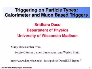
The Run II DØ Calorimeter Electronics Upgrade and its Performance. Shaohua Fu Columbia University for the D Ø Collaboration 2003 IEEE Nuclear Science Symposium Portland, Oregon October 19-25, 2003. Chicago . Booster. CDF. DØ. Tevatron. gap used to form trigger

E N D
The Run II DØ CalorimeterElectronics Upgrade and its Performance Shaohua Fu Columbia University for the DØ Collaboration 2003 IEEE Nuclear Science Symposium Portland, Oregon October 19-25, 2003
Chicago Booster CDF DØ Tevatron gap used to form trigger and sample baselines 3.56s p source Main Injector & Recycler (new) Run I 6x6 gaps superbunch 4.36s 2.64s 396ns Run II 36x36 Tevatron Run II • Successful Run I (1992-1996) • Run II upgrade • s : 1.8 TeV 1.96 TeV • Luminosity plans to FY2009: 4.4 fb-1(base)– 8.6 fb-1(design) Run I delivered luminosity ~ 120 pb-1 • Bunch structure: smaller bunch crossing time 2003 IEEE Conference, Oct 19-25
Central Calorimeter Inter-cryostat Detector Calorimeter End Caps DØ Upgrade • Upgrade Calorimeter readout electronics • Silicon and Fiber tracker with 2T solenoid magnetic field for central tracking and momentum measurement • Add Preshower detectors • Add scintillator detector in muon system for faster trigger • Pipelined 3-level trigger and new Data Acquisition system 2003 IEEE Conference, Oct 19-25
p y Central Tracking, Solenoid, CPS x z L. Ar. in gap 2.3 mm Drift time 430 ns Ur absorber 3, 4 or 6 mm Cu pad readout on 0.5 mm G10 with resistive coat epoxy Calorimeter Overview • Liquid argon sampling • Stable, uniform response, rad. hard, fine spatial seg. • L. Ar. purity important • Uniform, hermetic with full coverage • || < 4.2 ( 2), int > 7.2 (total) • Uranium absorber (Cu or Steel for coarse hadronic) • Compensating e/ response, dense compact • Run I Energy Resolution (from test beam) • e: (E/E)2 = (15%)2/E + (0.3%)2 (e.g. 3.4% @ 20 GeV) • : (E/E)2 = (45%)2/E + (4.0%)2 (e.g. 11% @ 20 GeV) ICD 2003 IEEE Conference, Oct 19-25
FPS ICD Intercryostat Detector (ICD) • Objectives • Improve coverage for the region 1.1 < || < 1.4 • Improve jet energy and missing energy • Maintain the performance in the presence of a magnetic field and additional material • Design • Scintillator based with phototube readout similar to Run I design. Re-use existing PMT’s. • 16 supertile modules per cryostat with a total of 378 scintillator tiles • WLS fiber read out of scintillator tiles • Clear fiber light piping to region of low field ~ 40-50% signal loss over 5-6m fiber • Readout/calibration scheme for electronics same as for L. Ar. Calorimeter but with adapted electronics and pulser shapes • LED pulsers used for PMT calibration • Relative yields measured > 20 p.e./m.i.p. 2003 IEEE Conference, Oct 19-25
Trig. sum BLS Card Bank 0 SCA (48 deep) SCA (48 deep) x1 Preamp/ Driver Filter/ Shaper Output Buffer Cal. cell ADC DAQ BLS SCA x8 SCA (48 deep) SCA (48 deep) Bank 1 Upgrade of Calorimeter Readout • Objectives and performance criteria • Accommodate reduced minimum bunch spacing from 3.56 s to 396 ns • Storage of analog signal for 4 s for L1 trigger formation • Generate trigger signals for Calorimeter L1 trigger • Maintain present level of noise and pile-up performance • Update for 55,000 readout channels • Replace signal cables from cryostat to preamps (110 30 for impedance match) • Replace preamplifiers, shapers, baseline subtraction circuitry (BLS) • Add analog storage (48-element deep Switched Capacitor Array (SCA)) • Replace timing and control system • Replace calibration system (new calibration pulser + current cables) • Keep Run I ADCs, crates and most cabling to minimize cost and time 2003 IEEE Conference, Oct 19-25
55296 hybrids 1152 boards preamp driver jFET 2” • Similar to Run I version except • Dual jFET front-end • Compensation for detector • capacitance • Faster recovery time New output driver for terminated signal transmission Preamplifier • New calorimeter preamp • Hybrid on ceramic, 14 species + 1 for ICD • 48 preamps on a motherboard • New low-noise switching power supplies in steel box 2003 IEEE Conference, Oct 19-25
1152 BLS boards 4608 daughter-cards 23040 SCAs L1 SCAs (2+2) L2 SCA Array of 48 capacitors to pipeline calorimeter signals Trigger Summers Shaper Trigger Drivers BLS and SCA • ADCs have 12-bit dynamic range. To achieve 15-bit dynamic range, SCAs have low and high gain path for each readout channel (8/1). • SCAs are not designed for simultaneous read/write operations. Two banks of SCAs, upper and lower, for alternate read/write operations. • No dead time for L1 trigger rate of 2-5 kHz. • Readout tower of 0.10.1 in , trigger tower formation 0.20.2 in for Level 1. 2003 IEEE Conference, Oct 19-25
6 commands (32) 96 currents Preamp box PIB Trigger Preamp board Pulse controller (Pulser) Pulser Interface: configuration management 6 active Fanouts with 16 switches: inductances form the pulse shape 12 Pulsers deliver: continuous current pulse height command determines pulse start Electronics Calibration System 2003 IEEE Conference, Oct 19-25
Single Channel Noise Noise of a single channel fitted with Gaus. Calorimeter Calibration (1) • Online calibration • Pulse shape measurements • Liquid argon purity • Reflection (impedance) measurements • Timing corrections • Debugging and noise studies • Linearity measurements and corrections • Offline calibration • Data quality control • Trigger performance • inter-calibration • Absolute EM scale fromW/Z, J/ and events • Electron ID, Jet ID and missing ET • Energy flow jet algorithm – track-calorimeter combination • Jet Energy Scale 2003 IEEE Conference, Oct 19-25
Noise w.r.t. cell capacitance (for different Preamp species) F E H G Preamp types E-H(5 pF feedback cap.) Sigma 100 / Mean (for gain 8) D C A B Preamp types A-D (10 pF feedback cap.) Calorimeter cell capacitance (pF) saturation Slope Slope from NEW run Electronics readout (ADC) 8 1 Slope of gain 1 from OLD calibration run Pulse height (DAC/1000) Linearity measurement Compare two runs taken 1 year apart Linearity is stable. Calorimeter Calibration (2) 2003 IEEE Conference, Oct 19-25
Z e+e Ncand = 1139 ∫L = 42 pb-1 DØ Run II Preliminary Z Br(Ze+e) = 275 9 (stat) 9 (syst) 28 (lumi) pb Physics Results • Preliminary results using Run II DØ calorimeter data have been shown at conferences, including QCD, Electroweak, B, Higgs, Top and New Phenomena physics. • Upgraded calorimeter performs well. We have about 200 pb-1 data. There are a lot more to come! 2003 IEEE Conference, Oct 19-25