Download
1 / 50
500 likes | 642 Views
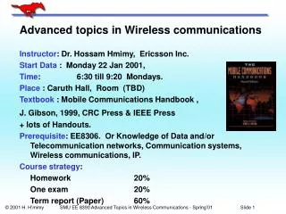
University of Canberra Advanced Communications Topics. Television Broadcasting into the Digital Era. Lecture 3 Digital Modulation Systems. by: Neil Pickford. Enabling Technologies. Source digitisation (Rec 601 digital studio) Compression technology (MPEG, AC-3) Data multiplexing (MPEG)

E N D
University of Canberra Advanced Communications Topics Television Broadcasting into the Digital Era Lecture 3 Digital Modulation Systems by: Neil Pickford
Enabling Technologies • Source digitisation (Rec 601 digital studio) • Compression technology (MPEG, AC-3) • Data multiplexing (MPEG) • Transmission technology (modulation)
Digital TV Transmission Technology • Transports data rates of around 20 Mb/s • Transports data in individual containers called packets • The transmission system is used to transport the information to the consumer. • The system protects the information being carried from the transmission environment • The transmission system is a “data pipe”
Digital TV Transmission Systems DTV & HDTV systems fall into three groupings • Europeans - Digital SDTV - 8 MHz on UHF - DVB-T (COFDM) • Americans - Digital HDTV - 6 MHz VHF/UHF - ATSC (8-VSB) • Japanese - Integrated Broadcasting - ISDB (BST-OFDM)
8-VSB - USA • Developed by the advance television systems committee ATSC • Developed for use in a 6 MHz channel • A 7 MHz variant is possible but has not been produced. • Uses a single carrier with pilot tone • 8 level amplitude modulation system • Single Payload data rate of 19.39 Mb/s • Relies on adaptive equalisation • Existing AM technology highly developed
COFDM - Europe • Developed by the digital video broadcasting project group - DVB • Uses similar technology to DRB • Uses 1705 or 6817 carriers • Variable carrier modulation types are defined allowing Payload data rates of 5-27 Mb/s in 7 MHz • Developed for 8 MHz channels • A 7 & 6 MHz variants have been produced and tested. • Can use single frequency networks - SFNs • New technology with scope for continued improvement & development
ISDB - Japan • Japanese are developing integrated services digital broadcasting (ISDB) • System integrates all forms of broadcasting services into one common data channel which can be passed by satellite, cable or terrestrial delivery systems • Video services • Sound services • Bulk data services • Interactive data services
ISDB - Concept • Uses Band Segmented Transmission - Orthogonal Frequency Division Multiplex (BST-OFDM)
Terrestrial Transmission Problems • Multipath interference - ghosts • Noise interference - snow • Variable path attenuation - fading • Interference to existing services • Interference from other services • Channel frequency assignment - where to place the signal
Digital Modulation - Functions • Spreads the data evenly across the channel • Distributes the data in time • Maintains synchronisation well below data threshold • Employs sophisticated error correction. • Equalises the channel for best performance
Digital Modulation Two techniques: • Conventional Single Carrier • 8VSB, QPSK or QAM • Multicarrier/Spread Spectrum • OFDM
8-VSB & COFDM - Spectrum 8-VSB COFDM
Sin(x)/x As power is an absolute quantity the negative amplitudes also resolve as real power Amplitude dB A Carrier phase or frequency modulated at a low symbol rate will exhibit a Sin(X)/X type spectral occupancy Frequency
Digital Modulation Low Symbol Rate Medium Symbol Rate High Symbol Rate Amplitude, dB Spectrum ofa Conventional Multi-Phase Keyed Carrier Fc at aSymbol Rate Fs Sin(X)/Xshaping Frequency Fc - Fs Fc + Fs Fc
BPSK Modulation I AXIS 0 1 180 Deg Phase Change
QPSK Modulation Q AXIS 1 0 1 1 QPSK Distance I AXIS 0 1 0 0
16QAM Modulation Q AXIS 1 1 1 0 1 1 1 1 1 0 1 1 16-QAM Distance 1 1 0 0 1 1 0 1 I AXIS 0 0 1 0 0 0 1 1 0 1 0 0 0 0 0 0 0 0 0 1
64QAM Modulation Q AXIS 111011 111111 1 0 1 1 111001 64-QAM Distance 110011 110111 110001 I AXIS 001110 001000 001100 0 0 000110 0 1 000000 000100
Hierarchical Modulation 0 0 Hierarchical Distance Q AXIS 1 1 1 0 1 1 1 1 1 0 1 1 1 1 0 0 1 1 0 1 QPSK Distance I AXIS 0 0 1 0 0 0 1 1 0 1 0 0 0 1 0 0 0 0
Digital Modulation Amplitude Typical Filtered Spectrum to give about half original bandwidth Occupied Channel Bandwidth Frequency Fc - Fs Fc + Fs Fc
Normal FDM Guard Band Amplitude, dB Carrier 1 Carrier 2 Frequency
Orthogonal Modulation Amplitude, dB Frequency
Orthogonal Modulation Amplitude, dB Frequency
COFDM - Orthogonal Carriers Frequency
Spectrum of COFDM DTTB Carrier Spacing 2k Mode 3.91 kHz 8k Mode 0.98 kHz AlmostRectangularShape 1705 or 6817 Carriers 6.67 MHz in 7 MHz Channel
OFDM Occupied bandwidth is: No. of Carriers x Spectral Width. Create with FFT Amplitude, dB Frequency Frequency Spectral Width 2k is 4x wider than 8k Fcentre
DIGITAL TERRESTRIAL BROADCASTING Distant transmitter Nearest transmitter Among the four Digital Broadcasting standards available, three are based on the Coded Orthogonal Frequency Division Multiplex modulation.... Why ? The Terrestrial Broadcasting has to cope with multipath propagation and Doppler effects: COFDM is the response for these impairments !
COFDM : HOW ? time RF Channel bandwidth frequency sub-band time segment frequency • 1 - Organize time & frequency partitions in the RF channel
COFDM : HOW ? time OFDM symbol Make sub-carriers orthogonal to avoid “inter-carriers” interference frequency • 2 - Spread sub-carriers over “time vs frequency” cells
COFDM : HOW ? Guard Interval duration Useful symbol duration time OFDM symbol frequency • 3 - Insert Guard Interval to avoid “inter-symbol” interference Guard interval introduces a first loss in transport capacity
COFDM : HOW ? OFDM Frame (68 OFDM symbols) time FFT time windows for receivers frequency • 4 - Insert “Synchronization Pilots” Helps Receivers to lock onto the signal Synchronization markers introduce the second loss in transport capacity
time frequency COFDM : HOW ? Protected DATA (convolutionnal error protection codes) • 5 - Prepare data to be carried on OFDM symbols DATA to broadcast Protection codes introduce the third loss in transport capacity
time frequency COFDM : HOW ? DATA to broadcast Protected DATA 0 1 0 0 1 • 6 - Map bits onto OFDM: Spread contiguous data bits over distant sub-carriers Create frequency diversity to improve robustness against fading
DTTB - Channel Estimation • The Terrestrial transmission channel is continuously varying (position & time) • Variations occur in Amplitude, Phase & Frequency • To correct for this variation Information needs to be added to the transmission to quantify the channels response at any instant - Pilots • Equalisers in the Digital receiver use this information to remove these transmission impairments
DVB-T - Carriers + Pilots Kmax = 1704 for 2K or 6816 for 8K Modulated Carriers Scattered Pilots 0.977/3.906 kHz SYMBOLS Kmin Kmax SYMBOLS IN SEQUENCE - 68 PER BLOCK.
DVB-T Super Frame TPS Carriers 17/68 34 50 1512: 1705 in 2k Frame 1 Frame 2 6048: 6817 in 8k Frame 3 Frame 4 Fixed Pilots 45/177 48 54 Co- Incident with Scattered pilots Super Frame 4 x 68 Symbols = N MPEG Packets
TPS Pilots • Transmission Parameter Signalling is added on selected carriers within the OFDM spectrum(17 pilots for 2k & 68 pilots for 8k) • TPS pilots Carry: • Frame Number in Super Frame: 00 / 01 / 10 / 11 • Constellation Type QPSK / 16-QAM / 64-QAM • OFDM Mode 2k or 8k • Constellation Mode Normal/Hierarchical + a value • Inner FEC Code rate (1/2, 2/3, 3/4, 5/6, 7/8) • Guard Interval (1/4, 1/8, 1/16, 1/32) • System Bandwidth (6, 7, 8 MHz)
DVB-T Transmission Frame 2k mode - 3906 Hz - Kmax=1704 8k mode - 977 Hz - Kmax=6816 Kmin=0 Carrier Spacing & Position Kmax Data TPS - Pilot Scattered Pilot Continuous Pilot Symbol Duration 256 us (2k) or 1024 us (8k)
DVB-T - Estimating the Channel A A B B=3/4A+1/4E C C=1/2(A+E) D D=1/4A+3/4E E E A to E - 1.024 ms (2k) - 4.096 ms (8k) For a varying transmission channel DVB-T estimation is 23.5 times faster than ATSC
DVB-T - Estimating the Channel A B C D E F G A B C D E F G B=2/3A+1/3D C=1/3A+2/3D E=2/3D+1/3G F=1/3D+2/3G A to D - 11.724 kHz (2k) - 2.931 kHz (8k) For a varying transmission channel DVB-T estimation is 23.5 times faster than ATSC
Estimation Rate DVB-T • Equaliser is updated every symbol period (256 us). 1/12 of data carriers are pilots • Full Channel estimate is available every 4 symbols (1.024 ms) Guard Interval • OFDM is better than Single carrier systems under Multipath Echo conditions due to the addition of a Guard interval in the modulation system. • The Guard interval is added onto the symbol time wasting some potential data capacity.
Guard Interval TG TU 1/8 TS 1/16 1/32 Transmitted Symbol Guard Useful Symbol 1/4
COFDM - Multipath TRANSMITTER A REFLECTIONS 1 Microsecond = 300 Metres DIRECT PATH SYMBOL PERIOD [1 ms] RECEPTION POINT SIGNAL Several µseconds disturbance from echoes. OFDM inherently resistant. 8VSB needs Time Domain Equaliser, symbol period short at 93ns
COFDM - Multipath TRANSMITTER A REFLECTIONS 1 Microsecond = 300 Metres DIRECT PATH GUARD INTERVAL SYMBOL PERIOD RECEPTION POINT SAFE AREA SIGNAL
COFDM - Pre-Echo GUARD INTERVAL SAFE AREA TRANSMITTER A REFLECTIONS 1 Microsecond = 300 Metres SYMBOL PERIOD RECEPTION POINT SIGNAL
COFDM - SFN TRANSMITTER B TRANSMITTER A REFLECTIONS 1 Microsecond = 300 Metres DIRECT PATH GUARD INTERVAL [Variable] SYMBOL PERIOD RECEPTION POINT SAFE AREA SIGNAL
Mobile Services • Antenna Performance • Poor Directivity, Low Gain • Multipath Dominated environment • Doppler • High Speeds for Main Roads and Railways • Low Speeds for Public Transport in Cities • Needs to be Rugged • Choose version of DVB-T that is suitable • Low Bit Rate, Low C/N, Long Guard Interval?
OFDM - Features • Multicarrier - many carriers sharing • Reduced C/N compared to Analogue • Resistant to echoes, Interference etc • Low symbol rate per carrier • ~ 1 kBaud: Long Symbol Period, can Extend with Guard Interval • With FEC becomes COFDM • Uses Fast Fourier Transform [FFT] • ”2k” and “8k” versions • Single Frequency Networks [SFN]