Download
1 / 26
260 likes | 405 Views
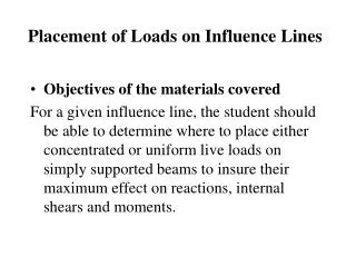
Generation of Influence Lines Using Statics. Objectives of the materials covered: The student should be able use the equations of statics to generate an influence line for reactions, internal shears, and internal moments at any point in a simply supported beam. Generation of influence lines.

E N D
Generation of Influence Lines Using Statics • Objectives of the materials covered: The student should be able use the equations of statics to generate an influence line for reactions, internal shears, and internal moments at any point in a simply supported beam.
Generation of influence lines Probably the most straight-forward way to generate an influence line is to use statics. The process involves • determining what influence line is desired, i.e. for one of the reactions, for an internal axial force, for an internal shear, or for an internal moment, • placing a unit load at various locations along the structure, • use statics to calculate the resulting reaction, axial force, shear, or moment corresponding to that position of the unit load, and • plot the resulting magnitudes on the beam at the current position of the unit load.
Influence Line for Reactions As an example, assume that the influence line for the left reaction of a simply-supported beam is to be generated. Place a unit load at the left end of the beam and solve for the magnitude of the resulting left reaction. By summing moments about the right reaction, the resulting magnitude for the left reaction is found to be 1.0. This value of 1.0 is then plotted on the beam at the current point of application of the load, namely over the left reaction.
Influence Line for Reactions Next, move the unit load to the center of the beam and again solve for the left reaction. By summing moments about the right reaction, the resulting magnitude for the left reaction is found to be 0.5. Plot this result of 0.5 at the current location of the unit load, i.e. at the center of the beam.
Influence Line for Reactions • Finally, move the unit load to the right end of the beam and by statics solve for the left reaction. For this case, Ra = 0.0. Again, plot this result at the current location of the unit load, i.e. at the right end of the beam. • The result is an influence line for the left reaction of a simply supported beam. Although we only found values at three points along the beam, we can connect these points to produce a continuous curve. Additional intermediate values could be found if desired, but will be found to lie on the straight line plotted
Influence Line for Internal Shear Now assume that we desire to generate the influence line for shear at the quarter point in the same beam. It is found in the same manner – namely, a unit load is moved across the entire length of the beam, and the resulting shear at the quarter point is computed and plotted. The process is detailed below: Position the unit load at the left reaction and solve for the resulting magnitude of the left reaction, then cut the beam of at the quarter point, where the shear V is desired, and draw a free body to expose the internal shear and moment at the quarter point in the beam. Solve for the exposed shear V using ∑Fv = 0. In this case we find that a unit load placed at the left end of the beam causes zero shear at the quarter point.
Influence Line for Internal Shear Now move the unit load just slightly to the left of the quarter point on the beam and solve for the resulting reactions. The left reaction is found to be 0.75 by summing moments about the right reaction. Again, draw a free-body of the left quarter of the beam, and solve for the exposed shear at the quarter-point by summing forces vertically. In this case, a resulting shear of 0.25 is caused by a unit load placed just to the left of the quarter-point. The direction of shear shown will arbitrarily be selected as negative. It should be emphasized that even though the load is moving across the structure, the free-body again, and always, must cut the beam at the quarter point, thus exposing the shear to be studied at that point.
Influence Line for Internal Shear • Now move the unit load just slightly to the right of the quarter point on the beam and solve for the resulting reactions. • Since the load is moved only an infinitesimal distance to the right of its previous position, the reaction remains = 0.75. However, even though this movement does not change the reaction, it now moves the unit load outside of the free-body used to solve for the resulting shear at the quarter point. • Thus it changes the resulting shear to a positive 0.75. Again note that length of the free-body remains L/4 for this, and for all other studies when determining the influence line for shear at L/4.
Influence Line for Internal Shear Next, move the unit load to the center of the beam and solve for the left reaction. Again, draw a free-body of the left ¼ beam, and solve for the exposed shear by summing forces vertically. In this case, a resulting shear of positive 0.5 is caused when the unit load is placed at the center of the beam. Note especially that this answer is to be plotted in the center of the beam.
Influence Line for Internal Shear • Note that many students, seeing the above free-body, think the resulting answer of 0.50 should be plotted at the quarter point, but this is not correct. Admittedly the resulting answer is a shear located at the quarter point, but the resulting answer is to be plotted at the current location of the unit load, i.e. at the center of the beam. Likewise, the two answers found when the unit load was positioned at the quarter point of the beam should both be plotted at the quarter point, since the unit load was located there at the time those answers were found – one slightly to the left, and one slightly to the right of the quarter point.
Influence Line for Internal Shear Finally, put the unit load at the right end of the beam and solve for the left reaction. Again, draw a free-body of the beam seen to the left of the quarter point, and solve for the exposed shear by summing forces vertically. In this case, a resulting shear of zero is caused by a unit load placed on the right end of the beam. We now have enough points to plot a continuous curve for the influence line for shear at the quarter point of a simply supported beam, as shown.
Influence Line for Internal Moment • Assume that we now desire to generate the influence line for moment at the quarter point in the same beam. It is found in the same manner – namely, a unit load is moved across the entire length of the beam, and the resulting moment at the quarter point is computed and plotted.
Influence Line for Internal Moment Position the unit load at the left reaction and solve for the resulting magnitude of the left reaction. Cut the beam at the quarter point, where the moment M is desired, and draw a free body to expose the internal moment at that point in the beam. Solve for the resulting exposed moment M = 0 using ∑ M = 0 about the quarter-point. In this case a unit load placed at the left end of the beam causes zero moment at the quarter point.
Influence Line for Internal Moment Now move the unit load just slightly to the left of the quarter point on the beam and solve for the resulting reactions. Again, draw a free-body of the beam to the left of the quarter point, and solve for the exposed moment at the quarter-point by summing moments about the quarter-point. In this case, a resulting moment of 0.1875L is caused by a unit load placed just to the left of the quarter-point. The direction of internal moment shown will arbitrarily be selected as positive.
Influence Line for Internal Moment Now move the unit load just slightly to the right of the quarter point on the beam and solve for the resulting reactions. Since the load is moved only an infinitesimal distance to the right of its previous position, the reaction remains = 0.75, and even though the unit load now moves outside the free-body used to solve for the resulting moment at the quarter point, the moment remains unchanged Again note that length of the free-body remains L/4 for this, and for all other studies when determining the influence line for shear at L/4.
Influence Line for Internal Moment Next, move the unit load to the center of the beam and solve for the left reaction. Again, draw a free-body of the beam to the left of the quarter point, and solve for the exposed moment by summing moments. In this case, a resulting moment of positive 0.125L is caused at the quarter-point due to the unit load placed at the center of the beam. Note especially that this answer is to be plotted at the center of the beam.
Influence Line for Internal Moment Note that many students, seeing the above free-body, feel the resulting moment of 0.125L should be plotted at the quarter point, but this is not correct. The resulting answer is indeed located at the quarter point, but the result is to be plotted at the current location of the unit load, i.e. at the center of the beam. Likewise, the two answers found when the unit load was positioned at the quarter point of the beam will both be plotted at the quarter point, since the unit load was located there at the time those answers were found – one slightly to the left, and one slightly to the right of the quarter point. However, both answers were the same.
Influence Line for Internal Moment Finally, put the unit load at the right end of the beam and solve for the left reaction. Again, draw a free-body of the beam seen to the left of the quarter point, and solve for the exposed moment by summing moments. In this case, a resulting moment of zero is caused by the unit load placed on the right end of the beam. We now have enough points to plot a continuous curve for the influence line for moment at the quarter point of a simply supported beam.
Other Examples for Influence Lines • Influence line for shear at the center of a simply supported beam:
Other Examples for Influence Lines • Influence line for shear at the right quarter of a simply supported beam:
Other Examples for Influence Lines • Influence line for shear for the right end of a simply supported beam:
Other Examples for Influence Lines • Influence line for moment at the center of a simply supported beam:
Other Examples for Influence Lines • Influence line for moment at the right quarter of a simply supported beam:
Other Examples for Influence Lines • Influence line for moment at 7/8 of L from the left reaction of a simply supported beam:
Teaming Problems Use statics to verify the influence line for shear at the quarter point for the doubly-overhanging simple beam shown below. Verify the results at x = 0, L/4, 2L/4, 3L/4, 4L/4, 5L/4, 6L/4, and 7L/4:
Teaming Problems • Use statics to verify the influence line for moment at the quarter point for the doubly-overhanging simple beam shown below. Verify the results at x = 0, L/4, 2L/4, 3L/4, 4L/4, 5L/4, 6L/4, and 7L/4.