Download
1 / 15
150 likes | 326 Views
+GF+ SIGNET 8860 Dual Channel Conductivity/Resistivity/TDS Controller. Two versions for simple stocking. Power requirements: 3-8860-AC : 100 to 240 VAC ± 10% , 50-60 Hz, 20VA or 10 to 26 VDC ±10%, regulated, 0.5 A max 3-8860 : 10 to 26 VDC ±10%, regulated, 0.5 A max only.

E N D
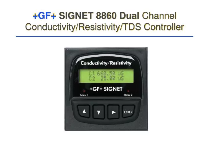
+GF+ SIGNET 8860 Dual ChannelConductivity/Resistivity/TDS Controller
Two versions for simple stocking Power requirements: 3-8860-AC: 100 to 240 VAC ± 10% , 50-60 Hz, 20VA or 10 to 26 VDC ±10%, regulated, 0.5 A max 3-8860: 10 to 26 VDC ±10%, regulated, 0.5 A max only.
Accuracy: 2% of reading(over a three decade range I.e. 0 to 1,000) Utilizing a sinusoidal drive (as opposed to squarewave drive) much greater range and accuracy is possible. The 8860’s patented (US pat. no. 5,708,363) measuring circuitry provides for a 3 decade range of operation with +/-2% of read accuracy. We accomplish this with plain metal electrodes (316 SS, Titanium or Monel)and avoid platinization of the electrodes to extend range (a costly and maintenance intensive process).
Multiple Functions Relay Functions:Low or High Alarmwith Hysteresis and Time DelayorProportional PulseofCond.,Temp, or FunctionorUSP Limitswith % margin below setpointand hysteresis 4-20 Functions:Fully spannable and reversiblewith adjustable endpoints.of Cond., Temp,or Function4 to 20 mA and Relay outputs have front panel display; and simulation capability! Unit Functions: Single or Dual Sensor InputThree isolated 4 to 20 mA outputs 2 SPDT RelaysPlus 2 additional SPDT Relays or Solid State Control outputs (switch selectable)
Temperature Compensation Methods • Standard Compensation Set 2%/Deg. CMost applicable setting due to the natural occurrence of salts in water and linear addition of salt to “conductance”. • Programmable from 0 to 10%/degree CSalts: typically 2%/ deg. C • Enter None for NO Temperature CompensationNecessary for USP and applications where automatic TC is not desired such as water used for its insulative or conductive properties.
Menu’s: Calibrate 1. Measurement setup Chan 1 Cell: Standard Custom > Chan 1 Cell: 0.01 0.1 1.0 10 20 > Chan 1 Set Temperature > Chan 1 Set Conductivity > Chan 1 Units > Repeats for Channel 2 Allows selection of Standard or Custom Cell values; (No limits placed in “custom” mode. Standard cell values are labeled: 0.01 0.1 1.0 10 20 Allows calibration of probe temperature. PT-1000 (error limited to +/- 20 deg. C) Allows calibration to a known value. All zero entry reverts both conductivity and temp to “factory calibrated” state. Allows display in uS, mS, Kohm, Mohm, PPM (TDS) or PPB (TDS)
Menu’s Calibrate 2. Function selection Function Ratio C1:C2 Ratio C2:C1 Diff C1-C2 Diff C2-C1 Reject C1-> C2 Reject C2-> C1 Only one function setting may be used. Ratio C1:C2 = C1/C2 Useful for determining Ratio of Cell 1 to Cell 2 Ratio C2:C1 = C2/C1 The inverse of above, used when sensors are wired or located in reverse order. Difference value C1-C2 The absolute difference in Unit of measure. Difference value C2-C1 Used when sensors are wired or located in reverse order. Percent Rejection: 100%(1-CH2/CH1) Displays filtration efficiency CH1 Feed/CH2 Product Percent Rejection: 100% (1-CH1/CH2) Displays filtration efficiency CH2 Feed/CH1 ProductUsed when sensors are wired or located in reverse order.
Menu’s: Calibrate 3. Loop setup Loop 1 Source: Chan 1 Cond > Loop 1 Rng: uS 0.0000 -> 2000.0 > 4 mA --> 20 mA Repeats for Loop 2 and 3 Allows selection of current loop source: Choices are: Chan 1 Conductivity Chan 2 Conductivity Chan 1 Temp Chan 2 Temp FUNCTION (Set in previous menu) Sets current loop range To reverse span (20 to 4) reverse left and right numbers
Menu’s: Calibrate 4. Relay/Open Collector setup Relay 1 Mode: High > Relay 1 Source: Chan 1 Cond > Relay 1 Setpoint 1500.00 uS > Relay 1 Hysterisis 50.00 uS > Relay 1 Delay: 020.00 secs > Allows operating Mode selection of relay or open collector output: Off, Low, High, USP, or Pulse Low = Active when process lower than setpoint High = Active when process above setpoint USP = Graduated setpoint based on USP allowances Pulse = Proportional pulse output from 0 to 400 pulses/minute Source selection: Chan1,2 Cond, Chan 1,2 Temp or Function Relay Setpoint (USP is high alarm with fixed limits with a percentage setpoint. A setting of 10 allows a ten percent variation from the limit) Relay Hysterisis or deadband (Delay allowed in Low, High, and USP modes from 0.0 to 6400 secs (1.777 Hrs.). Menu’s repeat for Relay 2 Relay/Open Collector 3 Relay/Open Collector 4
Menu’s: USP Defined USP (United States Pharmacopeia) requirements now allow for on-line conductivity measure of the water instead of offline tests for water quality. The limits are preloaded and control a high alarm when in USP mode, We are one of a few to offer this feature! Water Temperature Limit uS 0-5 deg C 0.6 uS 5-10 deg C 0.8 uS 10-15 deg.C 0.9 uS 15-20 deg C 1.0 uS 20-25 deg C 1.1 uS 25-30 deg C 1.3 uS 30-35 deg C 1.4 uS 35-40 deg C 1.5 uS 40-45 deg C 1.7 uS 45-50 deg C 1.8 uS 50-55 deg C 1.9 uS 55-60 deg C 2.1 uS 60-65 deg C 2.2 uS 65-70 deg C 2.4 uS 70-75 deg C 2.5 uS 75-80 deg C 2.7 uS 80-85 deg C 2.7 uS 85-90 deg C 2.7 uS 90-95 deg C 2.9 uS 100-105 deg. C 3.1 uS
New Relay Function for USP • USP relay function allows for an indication of unacceptable water quality across the full range of allowable conductance and temperature. • This is a high alarm, conductance greater than limits are not allowed. • A single percentage setpoint is allowed, 0 to 100%. (Percentage BELOW the allowable limit) • A programmable hysteresis in uS (0 to any value) prevents relay chatter.
Menu’s: Options 1. Display Contrast: 3 > Temp Display: oC > Channel 2 On > Power 60 Hz > Controls the display contrast from 1 to 5. 1 is the lightest, 5 is the darkest Allows display in degrees Celsius or Fahrenheit. Once calibrate in C or F it may be switched without need for re-calibration. Allows Channel two to be turned off, reducing the number of menu items if the second channel is unused Selects an internal filter to reduce effects of AC line noise. Select between 50 and 60 Hz according to the AC power standard in your area of use
Menu’s: Options 2. Input Settings Allows selection of temperature compensation Mode None = No affect on conductivity reading due to temperatureLinear = Linear correction due to temp i.e. 2% per degree C. Pure Water = Corrects for non-linear pure water characteristics. Allows entry of the proper TC slope term, typically 2% per degree C for natural water Allows averaging/response of the incoming signal Off = 1.5 secs., Low = 4.5 secs , High = 9 secs.Any change > 25% = 1.5 secs., Sets display decimal from none to four places. Channel 1 settings control “Function” decimal allowance for Ratio and Difference Chan 1 TC Mode Pure Water > Chan 1 TC Slope 2.00 > Averaging High > Chan 1 Decimal ***.** >
Menu’s: Options 3. Loop/Relay Options Loop 1 Adjust 4.00 mA > Loop 1 Adjust 20.00 mA > repeats for Loop 2,3 Relay 3 Active: Low > repeats for Relay 4 Test Loop 1 4.00 mA > repeats for Loop 2,3 Test Relay 1 On > repeats for Relays 2,3,4 Allows 4 mA endpoint adjustment: 3.8 to 5.00 mA Allows 20 mA endpoint adjustment: 19 to 21 mA Sets output Logic for Relay 3, Relay 4 (Open Collector 3, Open Collector 4) Allows Loop output control for testing or simulation. Range is from 3.60 to 21.00 mA and scrolls up or down by pressing up or down arrow buttons. Allows Relay control for testing or simulation. Relay toggles On or Off when up or down keys are pressed.