Download
1 / 15
150 likes | 151 Views
This discussion covers important comments and discussions regarding the first draft of the interlocking specification for LHC experiments including ATLAS, CMS, TOTEM, and LHCb. The topics include interlock masking, injection interlocking, response times, collimator movements, and Roman pots control.

E N D
Interlocking of LHC experiments Discussion of most important comments concerning the first draft of the specification : ATLAS, CMS, TOTEM, LHCb, LHC-OP group J. Wenninger LEADE / Exp. interlocking / J. Wenninger
Masking… • Without surprise all comments related to interlock masking insisted on the fact that the hardware interlocks from experiments should not be maskable. • This is perfectly acceptable and this issue has practically no operational consequences for the machine if the interlock signals work correctly : • The interlocks should only be activated when beam loss threatens to damage detectors. • Masking is only be permitted when the beam intensity is safe and should not lead to damage. masking is only allowed when there is no risk of damage, i.e. when one should never get an interlock ! • Note that this argument does not apply to movable devices like RPs / VELO that can be in the path of the beam and where masking must not be allowed ! • Important point : • If interlocks cannot be masked then they must be operational from day 1 ! • It is always possible to change the mask / no-mask option at a later stage. LEADE / Exp. interlocking / J. Wenninger
Injection interlocking • As you know, the foreseen beam interlock system combines in fact two functions that are not logically separated • Beam dump request, • Injection inhibit, because for almost all machine interlock systems, such a distinction is not relevant. LEADE / Exp. interlocking / J. Wenninger
Injection interlocking • Without surprise almost everyone prefers to have • a separation of the functionality concerning injection inhibit and beam dumping signals, • an implementation of the injection inhibit signal by ‘hardware’. • There are two possible implementations of a hardware interlock system to carry an injection permit signal : • An interlock loop similar to what is used for the beam permit system. • Direct connections to IR2 and IR8. • No budget is foreseen on the machine side for an injection interlock system spanning the entire ring. Estimated cost for the standard beam interlock solution : ~ 20-25 kCHF / experiment (crate + electronics) + price of optical fibre connection. LEADE / Exp. interlocking / J. Wenninger
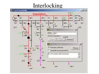
Injection interlocking BIC Injection permit loop (one loop for both beams) IR5 link to injection system link to injection system BIC BIC IR2 IR1 IR8 BIC LEADE / Exp. interlocking / J. Wenninger
USER_PERMIT signal changes from TRUE to FALSE a failure has been detected… beam dump request User System process Signals send to LBDS Beam Interlock system process Kicker fired Beam Dumping System waiting for beam gap all bunches have been extracted ~70μs max. 89μs max ~ 89μs > 10μs t3 t1 t2 t4 Response times • Response times ( last proton dumped) : • IR1 : 50 – 230 ms • IR2 : 70 – 200 ms • IR5 : 20 – 200 ms • IR8 : 35 – 215 ms • Depend on shortest distance to IR6. • Numbers may be subject to small changes (crate location & cable routing) LEADE / Exp. interlocking / J. Wenninger
Collimator movements • Collimators will have to be positioned at all times within a predefined tolerance window around their reference settings. • Settings depend on machine state/mode. • Final settings will be adjusted experimentally, and they are likely to evolve with time. • Under certain conditions (ramp, squeeze) the collimator will have to follow pre-programmed functions (position versus ‘time’) within pre-programmed tolerance windows. • OP crews will probably be allocated a small tuning range (if required). • The control system will compare demanded & actual position in real-time. • Presently it is foreseen to dump the beam if a collimator is outside its tolerance window. • It is important to realize that at high intensity/luminosity the most likely consequence of a bad collimator setting is a magnet quench ( beam dump, game over), any associated background increase is therefore very short ! LEADE / Exp. interlocking / J. Wenninger
Roman pots • The Machine Protection and Collimation WGs proposals for RP control: • RP control is integrated into the collimator control system. • RPs must be out in garage position under all conditions, except in ‘stable beams’ mode and with one possible exception – see later ! • The collimator control system ensures that the RPs are positioned in the shadow of the collimators by defining allowed position ranges. How these ranges are defined is likely to evolve with operational experience. • TOTEM / ATLAS have the possibility to directly request RP position changes to the collimator control system WITHOUT necessarily calling the control room. The request will be executed / rejected directly by the collimator control system according to the allowed position ranges. • I think that eventually the OP crews will not even interfere actively with the RP positioning that can be taken over by the experiments when the mode switches to stable beams. details must be worked out. LEADE / Exp. interlocking / J. Wenninger
Mode issues For 7 TeV operation, we have presently foreseen the following machine modes: • Adjust (taken over from LEP) : • Covers the period after the ramp when the beams are squeezed and brought into collisions. • This mode always follows the ‘ramp’, and precedes ‘stable beams’. • Stable beams (taken over from LEP) : • IRs squeezed (if applicable), beams in collision and collimators at physics settings. • Follows ‘adjust’. • Data taking conditions are somewhere between acceptable and excellent. • Op crews apply standard performance tuning, feedbacks may be up and running (if required). • Unstable beams (new) : • Covers periods where, due to an equipment failure or other uncontrolled conditions, the conditions no longer match ‘stable beams’, but the beams have not been dumped. • Data taking conditions may be bad / poor. • OP crews may have to apply more drastic tuning measure (potentially by trial and error). • This does not mean (as the name seems to imply) that beams are shaking around in the vacuum chamber ! • I personally do not like this name – it is misleading ! LEADE / Exp. interlocking / J. Wenninger
Modes • The machine mode is basically a flag to indicate what the OP crews are trying to do at a given moment. • There is no a priori guarantee that the machine and the beam will do what we would like them to do with 100% certainty. this statement is most relevant for the ‘stable beams’ mode. LEADE / Exp. interlocking / J. Wenninger
Transitions Ramp Adjust Stable beams Scheduled or un-scheduled Un-scheduled – fast /slow Scheduled Beam dump Unstable beams Unstable beams Scheduled transition for LHCb squeeze… Un-scheduled transition due to bad beam conditions. LEADE / Exp. interlocking / J. Wenninger
Out of stable beams / 1 • Scheduled transition : for ‘higher risk’ operation. • Timing is decided by OP crews, in agreement with experiments. At least in the early days, this implies contact by telephone ! • Hand-shake procedure over predefined signals perfectly meaningful. • Operation starts when all experiments give their OK (oral and/or by signal), or after timeout. • Un-scheduled slow transition : more or less like a scheduled transition • Possible case : slow and steady background increase over many minutes… LEADE / Exp. interlocking / J. Wenninger
Out of stable beams / 2 • Un-scheduled fast transition : • Beam conditions are degraded : high(er) backgrounds possible, beams may no longer be colliding, some equipment may have failed… • In this situation the OP crews must start acting ASAP in order to save the beam and restore good conditions – time may be limited ! • The change of the mode does not make any difference to the conditions – it is only a flag that acknowledges the actual machine conditions a hand-shake for the mode change is irrelevant ! actions may have to be taken immediately, irrespective of mode ! • If a mode change implies a beam dump from RPs or VELO then : • either we loose any chance to save the beam, • or the OP crews make drastic tuning in stable beams mode, • or we adapt the logic for RP/VELO interlocking. In the AB department many people do not like the fact that VELO / RPs should dump the beam if we have to change mode while their not (yet) out ! LEADE / Exp. interlocking / J. Wenninger
RP / VELO interlocking change A possible way out of this situation : • We define a new mode (for example ‘tuning’ ) to cover the situation where a previously stable beam requires more drastic actions. • RPs and VELO may only move towards the beam in stable beams mode (as before). • When the mode switches to ‘tuning’, RPs and VELO must automatically move out to their garage position, but must not dump the beam unless of course backgrounds are so high that they threaten to damage the detector. • In all other modes, RPs and VELO generate a beam dump if they are not in out/garage position. LEADE / Exp. interlocking / J. Wenninger
Outlook • For most points concerning interlocking, we will incorporate comments and update the document. • Another iteration must be performed for the ‘unstable beams’ transition, possibly affecting the definition of the modes LEADE / Exp. interlocking / J. Wenninger