Download
1 / 34
340 likes | 412 Views
Restructuring for delay optimization. Speaker : Guo-Jhu Huang Advisor : Chun-Yao Wang 2009.02.10. Outline. “ Rewiring Using IRredundancy Remove and Addition ” , Chun-Chi Lin Future work. Rewiring Using IRredundancy Remove and Addition. Introduction Notations and background IRRA

E N D
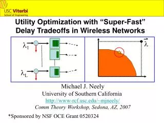
Restructuring for delay optimization Speaker : Guo-Jhu Huang Advisor : Chun-Yao Wang 2009.02.10
Outline “Rewiring Using IRredundancy Remove and Addition”, Chun-Chi Lin Future work
Rewiring Using IRredundancy Remove and Addition • Introduction • Notations and background • IRRA • Single alternative wire identification using the IRRA approach • SMA classification • SMA substitution • Experimental results
Introduction • RAR • A restructuring technique • Add some redundant wires and Remove a target wire • It will not change functionality of the circuit
Example of RAR a g2 b target wire g1 c o1 d g3 g4 o2 e Add redundant wire(g1 → g4) can make wire(c → g2) become redundant
Notation and background • Controlling value, cv(g) • An input of a gate g has a cv(g) if this value determines the output of g regardless of the other inputs • Non-controlling value, ncv(g) • An input of a gate g has a ncv(g) if this value cannot determine the output of g directly • AND gate has cv:0 and ncv:1
Notation and background a g2 b target wire g1 c o1 d g3 o2 g4 e • Dominator • The dominators of a wire w is a set of gates G such that all paths from w to any POs have to pass through all gates in G
Notation and background • For stuck-at 1 {0} fault test on a wire w(gs→gd) • Set cv at the source gs to activate the fault effect • Set ncv for all side inputs of w’s dominators to propagate the fault effect • If no test vector exists, the wire is redundant
Notation and background • Mandatory assignments (MAs) • The unique value assignments to gates required for a test to exist • MAs are obtained by • Activating the target fault effect • Setting side inputs of dominators • Implications
Notations and background g2 1 1 a 1 b g1 c 0 o1 0 d target wire g3 1 0 0/1 g4 o2 e 1 • An example ofMAs calculation • MAs are { g1=0, c=0, d=0, e=1, g3=1, g2=1, a=1, b=1 }
IRRA • Remove the irredundant target wire • Add another irredundant wire • To rectify the functionality of the circuit • The most important step in IRRA • How to derive the rectification network
Source MAs g2 1 a b g1 c 0 o1 0 d target wire g3 1 0 0/1 g4 o2 e 1 Source MAs are{c=0, d=0, e=1, g2=1} The MAs whose transitive fanin cone contains no other MAs
EAN & ERN • gd : a destination gate in the dominators of the target wire • Exact Addition Network (EAN) at gd • a network which minterms change from 0 to 1 after removing the target wire • Exact Removal Network (ERN) at gd • a network which minterms change from 1 to 0 after removing the target wire
EAN & ERN wt g1 a g3 g5 bc b O a 0 1 0 1 g2 c g4 • For example • Suppose the destination gate gd is g5 • EAN is the network composed of abc • ERN is the network composed of abc
EAN & ERN gdg(SMA)/gdf(SMA) : the cofactors of gd with respect to SMA in good/faulty circuits AND(SMA) : the product of all SMAs EAN = AND(SMA) ·gdg(SMA) ·gdf(SMA) ERN = AND(SMA) ·gdg(SMA) ·gdf(SMA)
EAN & ERN wt g1 a 0 g3 g5 1 b g2 c g4 • For example • gd is g5 • SMAs are { a=0, b=1 } • gdg(a=0,b=1)/gdf(a=0,b=1)=c/c • EAN at gd = ab·c·c = abc • ERN at gd = ab·c·c = abc
EAN & ERN • The rectification network at gd after removing the target wire is • (gd+ERN)·EAN • All minterms from 1 to 0 will be changed from 0 to 1 after ORing the ERN • All minterms from 0to 1 will be changed from 1 to 0 after ANDing the EAN • The order of adding ERN and EAN is irrelevant • (gd+ERN)·EAN = gd·EAN +ERN
EAN & ERN g5 SMAs … gdg(SMA) gdg(SMA) g5 1 1 SMAs g6 g6 … 0 0 1 g1 g2 0 gd redundant redundant 0 0 gdf(SMA) gdf(SMA) 1 EAN ERN gdf(SMA) = 0 g4 1 g3 gdf(SMA) = 1 … • Simplify the rectification network • The gdf(SMA) part is redundant
EAN & ERN SMAs SMAs … … gdg(SMA) gdg(SMA) gd EAN ERN … • After simplification • EAN at gd is AND(SMA) ·gdg(SMA) • ERN at gd is AND(SMA) ·gdg(SMA)
Single alternative wire identification SMAs SMAs … … gd gd gn gn … … D or 1 D or 0 • If gd has an MA D or 1{D or 0}, the value of gdg(SMA) will be 0{1} • ERN{EAN} is a constant 0 network • EAN{ERN} leaves the AND(SMA) term
Single alternative wire identification • If gd is a dominator which has an MA D{D} • AND(SMA) blocks the fault propagation • If gd is not a dominator which has a forced MA 1{0} • AND(SMA) violates the forced MA
Single alternative wire identification • To find single alternative wires of a target wire • AND(SMA) must be reduced to only one MA • SMA classification • SMA substitution
SMA classification • SMAs are classified into three types • Irredundant SMA • Redundant SMA • Semi-redundant SMA • The difference between redundant SMA and semi-redundant SMA • While performing the stuck-at fault test, irredundant SMAs in the AND(SMA) term are don’t care values or have to set specific values
SMA classification Initial rectification network g10 a wt b 0/1 c 0 a g1 e g2 b 0 0/1 c 1 g4 0/1 g11 a g3 0 g5 0/1 o1 o1 d 0 e 1 g6 0 a 0 e 1 g8 0 g9 0 o2 g7 b 0 e 0 1 SMAs are { a=0, b=0, c=1, e=1} c 1 For example
SMA classification • For example a g10 b c e c g4 g11 a g3 g5 o1 o1 d e g6 a : irredundant SMA b : irredundant SMA a e g8 g9 o2 g7 b e c
SMA classification • For example a g10 b c e 0/1 c g4 g11 a g3 g5 o1 o1 d 0 e 0 g6 a : irredundant SMA b : irredundant SMA a e g8 g9 o2 g7 b e : redundant SMA e c
SMA classification • For example a 0 g10 b 0 c 0/1 e c 0 g4 0 g11 a g3 0 g5 o1 o1 d 0 0 e g6 a : irredundant SMA b : irredundant SMA a e g8 g9 o2 c : semi-redundant SMA g7 b e : redundant SMA e c
SMA classification • For example a g10 b c e c g4 0 g11 a g3 g5 o1 o1 d 0 0 e g6 a : irredundant SMA b : irredundant SMA a e g8 g9 o2 c : semi-redundant SMA g7 b e : redundant SMA e c
SMA substitution 1 0 0 0 0 1 0 0 0 0 g1 g1 g1 g1 g1 a a a a a b b b b b 1 x 0 1 1 red. semi-red. Types of SMA substitution in an AND gate 0 1 1 1 1 0 1 1 1 1 g4 g4 g4 g4 g4 a a a a a b b b b b 0 x 1 0 0 red. semi-red. Types of SMA substitution in an AND gate If g1 implies g2, we say g1 can substitute g2
SMA substitution a g10 b c g4 g11 a g3 g5 o1 o1 d e • For SMA a: • g6=0 → a=0 • g8=0 → g6=0 • The substitution set for SMA a is { g6, g8 } 0 g6 0 a e 1 g8 0 0 g9 o2 g7 b 0 e 1 0 c 1 For example
SMA substitution a g10 b c g4 g11 a g3 g5 o1 o1 d e • For SMA b: • g7=0 → b=0 • g8=0 → g7=0 • The substitution set for SMA b is { g7, g8 } 0 g6 0 a e 1 g8 0 0 g9 o2 g7 b 0 e 1 0 c 1 For example
SMA substitution a g10 b c g4 g11 a g3 g5 o1 o1 d e 0 g6 0 a e 1 g8 0 0 g9 The intersection of the substitution sets of a and b is { g8 } o2 g7 b 0 e 1 0 c 1 For example
Experimental results [6] Y.-C Chen and C.-Y Wang, “An Improved Approach for Alternative Wires Identification,”in Proc. Int. Conf. Computer Design, pp.711-716,2005 Find alternative wires
Future work Study more papers