Download

1 / 31
310 likes | 318 Views
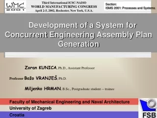
ISATP ’03 - THE 5th IEEE INTERNATIONAL SYMPOSIUM ON ASSEMBLY AND TASK PLANNING Session F4B: Production System Design. Development of a Design Procedure for Automatic Assembly System. Zoran KUNICA , Ph.D., Assistant Professor Professor Božo VRANJEŠ , Ph.D. Ivona T OMI Ć , B.Sc.

E N D
ISATP’03- THE 5th IEEE INTERNATIONAL SYMPOSIUM ON ASSEMBLY AND TASK PLANNING Session F4B: Production System Design Development of a Design Procedure for Automatic Assembly System Zoran KUNICA, Ph.D., Assistant Professor Professor Božo VRANJEŠ, Ph.D. IvonaTOMIĆ, B.Sc. Faculty of Mechanical Engineering and Naval Architecture University of Zagreb Croatia
CONTENT I. INTRO II. ASSEMBLY PLANNING TOOLS III. PLANNING SOFTWARE CONTENT IV. ASSEMBLY SYSTEM DESIGN: APPROACH& ASSUMPTIONS V. ASSEMBLY SYSTEM DESIGN: AN EXAMPLE VI. FURTHER WORK 3
I. INTRO Despite the significant advance in integration of engineering activities and technical systems, concurrent engineering approaches in integration of product design, assembly system design and assembly execution are still of pretty rare occurrence. Especially, CAD/CAE support for assembly system design is still underdeveloped. The goals of the research: • upgrading the planning methodology of automated assembly systems, • development of the CAE tools for planning. In this paper, we have tried to identify the procedure appropriate to assembly system design. 4
III. PLANNING SOFTWARE CONTENT • DFA & ASSEMBLY TECHNIQUES • ASSEMBLY SYSTEM/WORKCELL DESIGN (including: catalogues, CAD translators & importers) • DEFINITION OF POSITIONS • PROGRAMMING • PROGRAM OFF-LINE SIMULATION (COLLISION CHECK) • PROGRAM DOWNLOAD TO ROBOT/STATION CONTROLLER • PROGRAM EXECUTION • LAYOUT OPTIMISATION • PRODUCTION CYCLE OPTIMISATION • FINANCIAL METRICS • DIGITAL I/O AND WIRING DIAGRAMS 6
PLAN PRODUCT GENERATION DESIGN SYSTEM EXECUTION PROGRAMMING DESIGN CAM CAE CAD Development approaches CAD-based Programming-based Assembly-based 7
IV. ASSEMBLY SYSTEM DESIGN: APPROACH& ASSUMPTIONS The basis for assembly system design is appropriate ASSEMBLY PLAN, which defines: • assembly sequence, • assembly paths, • parts' positions (before and after assembly), • assembly operations. Assembly paths and operations imply principal technical solutions of particular assembly devices (device type, number, kinematics and dimensions) within assembly system. The equipment –devices, for assembly system is defined in three ways: • choosing among existing equipment, • modification of the existing equipment, • design of entirely new equipment. Devices are modelled interactively and automatically during CAD session, and using CAD libraries and catalogues, which possess parameterised design base of devices. The manufacturers or third party companies (Part Solutions) make equipment available for download on internet, also. 8
PROCESS STRUCTURE & OPERATIONS DEVICES CATALOGUE standard components DEVOTER non-standard components SYSTEM INTEGRATOR ADJUSTING OF DEVICE DESIGN A concept of the assembly system development 9
PRODUCT (ASSEMBLY) mechanism I – assembly paths mechanism II – components` motions ASSEMBLY SYSTEM standard components non-standard components • a product -- an assembly, exists as CAD model • assembly and disassembly are inverse issues • a product is a virtual mechanism, that should be recognized during planning stage • an assembly system is a complementary mechanism AAssembly process/system planning 10
An assembly planning environment should combine tools distributed in two levels: 1. pretools within activities prior to assembly planning, 2. assembly planning CAE component (posttool) that follows product design process. Assembly planning and activities of product design 11
Discrepancy in orientation: natural orientation of the part (A), technological orientation (B), orientation required in a product (C) 12
ASSEMBLY PLAN GENERATION OPTIONS Product class Connectivity On check Off Automatic generation On of assembly sequence Off Automatic generation On of assembly system layout Off . . . Planning procedure should be analysed as a combination of automatically and interactively generated elements. Example of definition of plan generation parameters 14
Variants/variations of products TThompson's examples of variations of living organisms (1917) Duerer's (1471-1528)examples of variations of living organisms Two solutions of the samemechanism(Blanding, 1999) 15
Variations of assembly process The assembly process can be represented and modelled using generic structures – generic plans. The structures show the space and time possibility of the assembly process realisation. Some of the structures for a product with six parts (Beneath the graphical presentation of each structure the structure’s numerical code is given.) 16
Hi6 Hi4 Hi3 Hi5 Hi2 • Variants of product`sinitial orientation xz – horizontal plane 17
Line assembly (L = 8639,487 mm) Variants of parts’layout . Hi5 Rotary-table (D = 1234,212 mm) Hi4 z distance Hi5-Hi6: 5924,22 mm Hi2 Hi3 18 Hi6
Savings in space and equipment! Treatment of identical parts in a product Disassembled product... Without taking into account identical parts... Taking into account identical (yellow) parts... 19
Variants of equipment’s manufacturer FANUC LR Mate 100i AdeptSix 300 ABB IRB 140 • Variants... variants... etc. ... 20
VI. ASSEMBLY SYSTEM DESIGN: AN EXAMPLE • A product– assembly Hi5 100 mm Hi3 75 mm Hi2 Hi7 75 mm xz – horizontal plane 21
Hi5 Hi7 Hi3 Hi2 tHi7 = 397 mm tHi5 = 397 mm tHi3 = 265 mm tHi2 = 265 mm Disassembly simulation (sequence and paths, and positions of parts before assembly) Top view 22
Variant I There are four identical pneumatic cylinders. The cylinders push parts from their positions before assembly, towards required final positions, to make the assembly. The cylinders are pretty long, implying a larger necessary space. The parts come in the assembly process in ordered state -- magazines. Assembled product is removed from the assembly spot by a murder hole. Double acting cylinder DSNU-25-400P-A 23
Variant II Almost the same as the variant I. There are also four identical cylinders, but of another type – with shorter strokes. In that way it was possible to place parts closer to the assembly spot (correction of position values obtained by assembly plan). The cylinders in both variants (I & II) are chosen among many available, and applicable to this specific situation. Double acting cylinder DSW-32-P-B 24
Variant III The assembly system consists of four identical manipulators, each containing two linear modules, and having identical grippers. Additionally, there is also a pneumatic cylinder for the part Hi7. Three manipulators with their grippers carry the parts to the required final positions. The fourth manipulator takes the part Hi7 and delivers it at the pneumatic cylinder, which pushes the part in its final position within the product. Since the manipulators have only two DOFs, included pallets should be movable (two DOFs). Linear module HMP-20-400 25 Parallel gripper HGP-35-10
Variant IV Vacuum gripper VAS-30-1/8-PUR The variant IV is similar to the variant III, except a robot equipped with a vacuum gripper is added to the part Hi7, so the cylinder from the variant III is obsolete. 26
Variant V The variant V is the enhancement of the variants III and IV. The main difference -- three robots (with four DOFs each) are used in the variant V, instead of manipulators in the variants III and IV. Consequently, movable pallets are no longer needed. 27
Variant VI Three identical robots from the variant V are replaced with one single robot. The savings in equipment cost and space are obvious, but assembly cycle will be longer. 28
Variant VII Only one single robot with four DOFs, will assemble the whole product. Since the part Hi7 requires different gripper than the rest of the parts, the assembly system should involve a possibility of gripper change. Neglecting the gripper change subsystem, the variant VII carries further cutting of equipment and space costs. However, the assembly cycle becomes longer. 29
S. Freud VII. FURTHER WORK • Detailed variant design of devices, including: • analysis and optimization of (dis)assembling paths (directions and lengths), • simulation of assembly operations and assembly techniques (forces, deformablejoints - snap fitting, ...). • Implementation of assessment criteria. • Automation of the design procedure. • Experiments with concurrent generation of assembly plans and systems. • Modelling of CE planning situations and roles (procedures, protocols and data sharing). • Human planner's mental activities and behavior -- conscience and non-conscience (intuitive) aspects of the planning. & Eric Berne`s transactional analysis 31