Download
1 / 27
270 likes | 493 Views
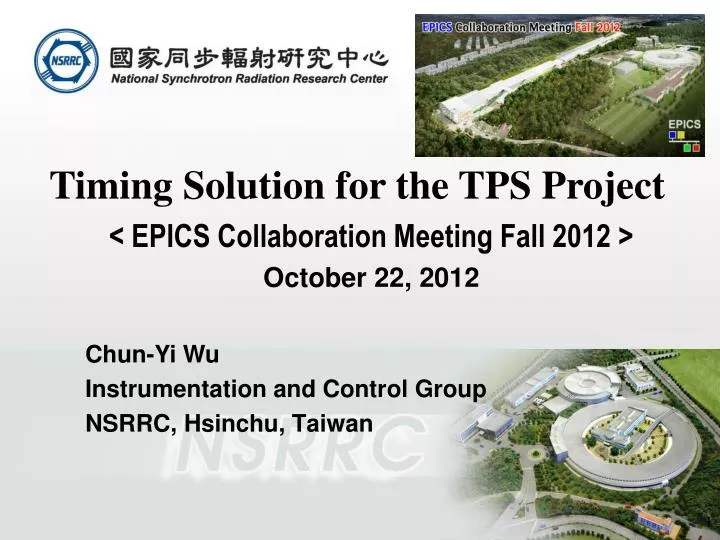
Timing Solution for the TPS Project < EPICS Collaboration Meeting Fall 2012 > October 22, 2012 Chun-Yi Wu Instrumentation and Control Group NSRRC, Hsinchu , Taiwan. Outline. TPS RF reference d istribution TPS timing system Hardware Timing system distribution network

E N D
Timing Solution for the TPS Project < EPICS Collaboration Meeting Fall 2012 > October 22, 2012 • Chun-Yi Wu Instrumentation and Control Group NSRRC, Hsinchu, Taiwan
Outline • TPSRF reference distribution • TPS timing system • Hardware • Timing system distributionnetwork • Timing system diagnostic • Sequence RAM management • Summary
TPSRF Reference Distribution Master Clock 10.000 MHx Timing System RF Distribution 15 dBm ~ 35 m Transmitter Transmitter Transmitter Transmitter Transmitter Fiber Links with Drift Compensation ~ 250 m ~ 150 m ~ 125 m ~ 100 m G.652D SM Fiber @ 1550 nm LinacLLRF Receiver Receiver Receiver Receiver Receiver Testbed 5 ~ 15 dBm 5 ~ 15 dBm 5 ~ 15 dBm 5 ~ 15 dBm 5 ~ 15 dBm Booster Synchrotron LLRF Diagnostics BBF Beamlines…etc. SRF LLRF #1 SRF LLRF #3 SRF LLRF #2
RF Reference Distribution – Performance Test Fiber Link Output ~ 49 fsec (10Hz~1 MHz) Master Oscillator Output ~ 36 fsec (10Hz ~ 1 MHz) Added Jitter =SQRT(492-362) ~ 33 fsec(<< 0.1° RF phase at 500 MHz) It’s sufficient for TPS RF stability requirement Temp Time (Hour) Preliminary Long-term Drift Test (Limited by Measurement System Performance)
Timing System Solution • Main Parameters • RF : 499.654 MHz • Booster revolution clock : 603.445 kHz (864 bucket) • Storage ring revolution clock : 578.303 kHz (828 bucket) • Coincidence clock : 25.14 kHz • Event Clock : 124.9135 MHz • Jitter : < 20 ps (cPCI-EVR), < 10 ps (cPCI-EVRTG) • Resolution : 8.0054 ns • Repetition rate : 3 Hz • Hardware form fact • 6U compactPCI • EVG • EVR • EVRTG • Fan-Out Concentrator • PCIe • EVR • PXIe • EVG (available in the mid of next year, R&D purpose for possible TLS upgrade) • EVR
Timing System Hardware Fibre Fan-Out Concentrator cPCI-EVG-300 PXIe-EVR-300 Universal I/O TTL Interlock Input ModuleUniversal I/O TTL Input UNIV-TTLIN Universal I/O TTL Output UNIV-TTL Universal I/O TTL Output Module w/ Delay Tuning Universal I/O NIM Output UNIV-NIM Universal I/O LVPECL Output Module Universal I/O LVPECL Output Module with Delay Tuning Universal I/O HFBR-1414 Output UNIV-HFBR-1414 Universal I/O HFBR-1528 Output UNIV-HFBR-1528 cPCI-EVR-300 cPCI-EVRTG-300 (e-Gun Trigger) Universal I/O modules PCIe-EVR-300 GUN-RC-203/300 Interface Board IFB-300
Fanout Concentrator Fanout Concentrator Fanout Concentrator Fanout Concentrator Fanout Concentrator Timing System Distribution Network Fanout Concentrator 1st level x 1 2nd level x 4 3 rd level x 24 Total 29 units Master RF Frequency Standard • The propagation delay time due to fiber is ~5 ns/m. • In order to achieve almost simultaneous receipt of event codes at EVRs. All fiber lengths are equal. Timing Master EVG EVR-300 Linac Trigger EVRTG-300 Gun Trigger CIA 01 Fanout Concentrator EVR-CIA01 Drift Compensator CIA 02 Fanout Concentrator EVR-CIA02 EVR-Booster PS EVR-RF 1 350 Meter OM3 Fiber EVR-RF 2 60 Meter OM3 Fiber EVR-RF 3 EVR-Booster RF CIA 23 Fanout Concentrator EVR-BBF EVR-Linac EVR-CIA24 EVR-LTB/BTS Diag CIA 24 Fanout Concentrator EVR- Injection/Extraction #1 400 Meter environmental temperature sensing OM3 Fiber EVR- Injection/Extraction #2 EVR-CIA EVR-CSCR
Timing System Health Monitoring (TDC + Oscilloscope + Lock-in Amplifier) Highland Technology, Inc. T680 compact Ethernet/USB time to digital converter TIC Mode (15.25 picosecond resolution with 48 bit range) Sync Start TDC Microcontroller SR Frev TDC BR Frev TDC Ethernet ……. TDC ……. Oscilloscope (waveform observation) High frequency Lock-in Amplifier (drift measurement)
What operation mode will be delivered in timing system? • Various operation mode • Accelerator subsystem test mode • Individual subsystem(or devices) trigger control for debug mode • Bunch mode selection • Single shot injection • Continue injection • Repetitive rate decimation for specific trigger. • Warm up trigger for specific device. • Bucket addressing. • Top-up injection for desired fill pattern. • Top-up injection with filling pattern feedback. • …. How to handle these operation modes? • => By well managing sequence RAM of EVG
Example of reference events Transfer to SR 3 GeV – BR Ext Energy Ramping 150 MeV – BR Inj t BR Cycle 333.333 msec t c d e g a a b f BTS a. T-ZERO at 0 msec b. BR-HW-TRIG at 1 msec c. LINAC-PRE-INJ at 10000 msec d. BR-PRE-INJ at 10000 - 10 msec e. BR-PRE-EXTR at 160000 - 5 msec f. SR-PRE-INJ at 160000 - 5 msec g. SR-INJ at 160000 - 5 msec Linac LTB Gun Booster Ring Storage Ring
Booster Synchrotron Power SupplyWaveform Plans Operation Modes ~ 1034 A (3 GeV) DCwith Single Shot - RF OFF - RF ON DC with repetition rate control ( 3 Hz trigger, cycles between shot-to-shot: 0 ~ 1000 ?) - RF OFF - RF ON ~ 50 A(150 MeV) BR Injection (3 Hz Trigger) “Single-shot or adjustable rep-rate is planed to support by timing sequencer” ~ 1034 A Ramp with Single Shot - RF ON Ramp with repetition rate control ( 3 Hz trigger, cycles between shot-to-shot: 0 ~ 1000 ?) - RF ON BR Ext 10 msec 23.333 msec 150 msec 150 msec ~ 50 A BR Injection 333.333 msec T-ZERO (Sync to mains frequency) T-ZERO
Pulsed Magnets Trigger Scheme 300 msec half-sine BR Injection/ Extraction Septum Storage Ring Injection Septum BR Injection, Extraction Septum and SR Injection Septum Trigger event 8 nsec/step BR Injection/Extraction Kicker 10 msec is used to compensate for difference of pulsed magnet PS 1000 nsec rectangular BR Injection/Extraction Kicker Trigger event Delay (~ 149.5 msec) 8 nsec/step SR Injection Kicker 5180 nsec half-sine SR Injection Kicker Trigger event Delay (~ 147.5 msec) << 1 nsec/step
Pulsed Magnets Trigger Scheme – cont. Demi’s Fanout EVR-300 BR Injection Event BR Injection Septum Trigger Delay ~ 10 msec Delay ~ 159.5 msec BR Injection Kicker Trigger BR Extraction Event Delay ~ 10 msec BR Extraction Septum Trigger K1 Delay ~ 159.5 msec BR Extraction Kicker Trigger K2 Delay ~ 159.5 msec SR Septum Trigger Event SR Injection Septum Trigger Delay ~ 10 msec Oscilloscope Trigger Delay ~ 157.5 msec SR Kicker Trigger Event K1 T560 DDG Delay ~ 157.5 msec K2 SR Injection Kicker Trigger Delay ~ 0 msec K3 K4 SR Pinger Trigger Event Delay ~ 0 msec Horizontal and Vertical Pinger
Sequence RAM of EVG Sequence RAM of EVG : allows generation of well defined event sequence with precise relative delays
Sequence RAM – Individual Device Trigger Control ON Every Shot OFF ON LINAC-PRE-INJ RAM Address Delay Time Timestamp Event Code Timestamp Event Code Timestamp Event Code LINAC-PRE-INJ Refresh on 3 Hz rate If LINAC-PRE-INJ active => ON If LINAC-PRE-INJ inactive => OFF Null Event Code Stop Sequence RAM
Sequence RAM Programming at Every Cycle GeV 3 ~ 1034 A (3 GeV) Booster Dipole Magnet Current BR Ext 10 msec 150 msec 23.333 msec 150 msec ~ 50 A(150 MeV) 0.15 T-ZERO BR Inj Window available for Sequence RAM program Active Sequence RAM Sequence RAM playing Updated SR Current Cycle N Sequence RAM Trigger Cycle N+1 Sequence RAM Trigger Sequence RAM Stop
Machine Cycle Definition following state LinacPre-injection Linac RF ON Booster Pre-injection Linac RF ON Booster Injection Septum ON Booster Injection Booster PS ON Linac RF ON Booster Injection Septum ON Booster Injection Kicker ON E-Gun ON Booster Pre-extraction Booster Extraction Septum ON Booster Extraction Booster Extraction Kicker ON SR Pre-injection SR Injection Septum ON SR Injection SR Injection Kickers ON …….
Injection Modes Beam Modes: Single Bunch Mode (SB Mode) Per Bunch Current How many bunches (for multiple isolated bunches) Bucket Address Bucker address jump Multi-Bunch Mode (MB Mode) Current Bunch train length Bucket Address Camshaft Mode Combine SB and MB Mode Top-up Mode Support all above Mode (s)
Injection Control related EPICS IOCs Timing Master IOC (Include Injection Control) Timing Backward Link IOC LI-TI Gun Timing, Linac Timing, Timing Diagnostic Injection Control IOC E V G Linac E V R Gun E V R E V R Uplink E V R Booster Main PS Timing IOC E V R Timing Fanout CA access Booster RF Timing IOC E V R Injection Command: Modes Cycle Time … etc. Suggested next bucket address for injection E V R NPCT IOC (Beam current, Beam lifetime, …) Filling PatternIOC (Bunch current, Bunch lifetime, …) Injection and Extraction Pulsed Magnets Power Supply Timing IOC Desired Filling Pattern
TPS Timing Sequencer Structure (SNL Option) Client OPI Application (EDM, MATLAB) Injection Control GUI (Channel Access Client) Beam Current Filling Pattern TPS Control Network Channel Access Server/Client EPICS Sequencer (SEQ/SNC) PV API Global Timing Control PVs Database Device Support 3 Hz Interrupt Event Generator (cPCI EVG-300)
Issue on Bucket Addressing BR-Bucket Address 35 827 0 1 2 3 4 5 6 7 8 9 10 BR Rev-CLK SR-Bucket Address 863 0 1 2 3 4 5 6 7 8 9 10 827 SR Rev-CLK COINC-CLK Bucket Address Scheme: (1) Timestamp of sequence RAM in 8 nsec/step (2) Gun delay in 2 nsec/step (cPCI-EVRTG-300) BR Injection or ExtractionTrigger Timestamp of sequence RAM increment = SR Bucket Address MOD 4 Gun delay in cPCI-EVRTG-300 = SR Bucket Address % 4 Gun delay Timestamp in Sequence RAM + 0 Timestamp in Sequence RAM + 3 Timestamp in Sequence RAM + 1 Timestamp in Sequence RAM + 2
Example of Bucket Addressing Process Bucket Address: 0 Bucket Address: 132 Bucket Address: 133 Bucket Address: 134 RAM Address Delay Time Timestamp Event Code Timestamp Event Code Timestamp Event Code Timestamp Event Code Only change timestamp of injection beam related events Timestamp increment + 33 + 0 + 33 + 33 E-GUN Phase Shift (cPCI-EVRTG-300) + 0 nsec + 0 nsec + 2 nsec + 4 nsec
Functional Flowchart of the Timing Sequencer Initialization (Sequence RAM Default) Enable Sequence RAM Wait for Interrupt Disable Sequence RAM If abort beam injection Cycle Count = 0 CycleCount > 0 Mode Standby Test Linac Only BR Injection SR Injection SR Top-up Injection Pinger ----- ----- ---------- ---------- ---------- -------- Beam Cycle ? Yes No ----- ----- ---------- ---------- ---------- -------- ------- ------- ----- ----- ---------- ---------- ---------- -------- ------- ------- ------- ------- Cycle Count-= Cycle Count -1
Beamline and Experimental Station Timing Interface to Nearby CIA (OM3 Fiber Pair) Standard Interface Only available for users who need low jitter clock Fiber Patch Panel @ Beamline Rack 499.654 MHz PCIe-EVR-300 91.7 mm x 79.2 mm Control Network Timing Network Libera Sync TX EPICS IOC (Gateway, Phase Sifter Control, …etc.) PCIe-EVR-300 Interface Board IFB-300 Interface Board IFB-300 Libera Sync RX ReSync Phase Shifter (I/Q type?) UNIV I/O 0 (TTL or NIM) Short Gate UNIV I/O 3 (TTL or NIM) SR Clock 1/6, 3/20 UNIV I/O 1 (TTL or NIM) Long Gate UNIV I/O 4 (TTL or NIM) Injection 83.2757 MHz or 74.9481 MHz 1 ~ 10 KHz (Laser Amplifier) 499.654 MHz
Top-up Gating Timing Signals of Beamline Short GATE Short GATE Short GATE SR Inj BR Inj NO INJECTION! TOP-UP-ON TOP-UP-OFF ~ 170 msec 10 msec TOP-UP-OFF T-Delay T-Width Short GATE Long Gate Long GATE SR-CLK SR Clock TOP-UP Mode ( 3 Injection Cycles) Timing Signals available for Beamlines
Summary • The first lot of EVG/EVR/Fan-out concentrator modules was received in December 2010 • Setup test system has been started from February 2011 • Linac timing is ready for commissioning of the TPS linac in April 2011 • First prototyping of timing sequencer test by Matlab scripts was tested in 2011. • Implementation of timing sequencer base on EPICS SNL is on-going. • Installation of TPS timing system is scheduled in the 3rd quarter of 2013. • Full scale Test of TPS timing system is scheduled in late2013.
TLS TPS Thank You for Your Attention