Download
1 / 264
2.66k likes | 2.89k Views
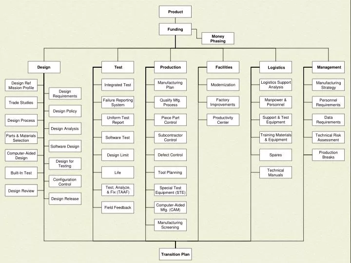
Product. Funding. Money Phasing. Design. Test. Production. Facilities. Management. Logistics. Logistics Support Analysis. Manufacturing Plan. Manufacturing Strategy. Design Ref Mission Profile. Modernization. Integrated Test. Design Requirements. Factory Improvements.

E N D
Product Funding Money Phasing Design Test Production Facilities Management Logistics Logistics Support Analysis Manufacturing Plan Manufacturing Strategy Design Ref Mission Profile Modernization Integrated Test Design Requirements Factory Improvements Manpower & Personnel Qualify Mfg. Process Personnel Requirements Failure Reporting System Trade Studies Design Policy Support & Test Equipment Data Requirements Uniform Test Report Piece Part Control Productivity Center Design Process Design Analysis Training Materials & Equipment Technical Risk Assessment Subcontractor Control Parts & Materials Selection Software Test Software Design Production Breaks Computer-Aided Design Defect Control Spares Design Limit Design for Testing Technical Manuals Tool Planning Life Built-In Test Configuration Control Test, Analyze, & Fix (TAAF) Special Test Equipment (STE) Design Review Design Release Computer-Aided Mfg. (CAM) Field Feedback Manufacturing Screening Transition Plan
Funding INTRODUCTION FOR FUNDING CRITICAL PATH TEMPLATE Over the years, the Department of Defense and the Military Services have been struggling to improve the acquisition process. There has been a seemingly endless proliferation of “blue ribbon” panels, ad hoc reviews, summer studies, task forces, and audits, whose memberships consisted of the most respected representatives of Government and industry. Many of these efforts were mandated congressionally, but the increasing congressional focus (General Accounting Office (GAO) reports and staff member inquiries) on
Funding Cont’d DoD acquisition programs indicates that Congress is not convinced that the overall objective, namely, “more bang for the buck,” is being accomplished. There is no doubt that past studies and reviews have provided many practical recommendations and those that were acted upon helped formulate current procedures for the DSARC process and the PPBS. Yet, there is still concern whether the taxpayer’s money is being well spent and whether our Armed Forces are being provided equipmentthat works when needed. Why do we have so many cost overruns and why does our operating equipment fail so frequently?
Funding Cont’d The answers are not simple. Some of the more lofty answers pertain to the increasing complexity of our hardware, greater administrative reporting burdens, changes in administration policy from one election to the next, and variations in the level of our international military commitment as it influences and is influenced by the existing attitude of the American public. However, there are at least three answers that are not so lofty and over which we can exert significant control. One relates to the need for more discipline in the technical side of the acquisition process, that is, more attention to the engineering fundamentals of design,
Funding Cont’d test, production, and supportability; this answer is the basic purpose of this Manual and is well described in the Preface and Introduction. A second answer involves the critical resource of personnel and is discussed in a separate template in the Management section. The thirdanswer is sound funding policy. In order to avoid “biting off more than we can chew,” and because there are many facets to funding policy concerns, the following template on money phasing is confined to research, development, test, and evaluation (RDT&E), and initialproduction funding.
Money Phasing AREA OF RISK Inadequate RDT&E funding is, of course, an obvious major risk area. Aside from this “quantity” issue, however, there are the other funding risk areas that deal with the phasing of money: (1) inadequate early RDT&E funds, and (2) inadequate early production funds during the latter phases of development (initial production funds (IPF) and long lead). Risk is aggravated by authorizing development without production in mind. The development decision is a commitment to production that must be supported by properly phased funding.
Money Phasing Cont’d PERCENT OF TOTAL RDT&E COSTS PER YEAR TIME OUTLINE FOR REDUCING RISK • If the all-important design and engineering effort is to be funded adequately, provide a reasonable proportion of total RDT&E funds in the early years. Figure 2-1. is a representation of an idealized RDT&E funding profile. Figure 2-1. What We Should Do (RDT&E Funding Profile)
Money Phasing Cont’d PERCENT OF TOTAL RDT&E COSTS PER YEAR TIME Rarely, however, are funds provided on this type of schedule. Early dollars are hard to find and the profile shown in figure 2-2. is a much more typical situation. This condition is aggravated when programs are started on short notice. A significant initial subset of this profile is the RDT&E funding spent on production preparations. If this funding profile is changed, the impact on transition must be assessed. Figure 2-2. What We Do (RDT&E Funding Profile)
Money Phasing Cont’d PERCENT OF RDT&E COSTS PER YEAR WHAT WE SHOULD DO WHAT WE DO TIME Figure 2-3. combines these idealized and actual funding profiles, and the shaded area represents a “design and engineering gap” from which the program cannot recover by application of later funds. The first type of funding risk, therefore, can be ascertained by comparison of a program’s funding profile with those of figures 2-1. and 2-2. Figure 2-3. The “Design and Engineering” Gap
Money Phasing Cont’d ALTERNATIVE PRODUCTION FUNDING PROFILES RDT&E TOO EARLY TOO LATE • The second type of risk reduction involves the early commitment of production funds-while development is still ongoing-for tooling, long lead materials, and production line startup. Figure 2-4. shows a graphic representation of the needed buildup of production funds during RDT&E phase down. The “fly before buy” school of acquisition policy tends to drive to the “too late” line. Excessive concurrency can result in unwise commitments indicated by the “too early” line. For all programs there will be an optimum middle ground that results in low RDT&E risk and a controlled “transition to production” (shaded area). COST Figure 2-4. Funding Profiles (RDT&E and Production)
Money Phasing Cont’d TIMELINE Early availability of enough funding from the RDT&E and procurement appropriations is essential for a smooth transition from development to production and early deployment. The proper focus must continue during each annual budget cycle. Without a proper funding profile, it will be impossible to keep the program in technical balance. PROGRAM PHASE DEPLOY- MENT JMSNS I II IIIA IIIB TEMPLATE ACTIVITY Funding Money Phasing
Design INTRODUCTION FOR DESIGN CRITICAL PATH TEMPLATES High risk of failure of Government material acquisition programs occurs at the outset of the design process. While some level of risk associated with a new technical concept may be unavoidable, historically this risk has been magnified by the misunderstanding of the industrial design disciplines necessary to turn the concept into a mature product. The Government and its contractors must share equal responsibility for this misunderstanding. The industrial proposal and Government source selection process provide the last
Design Cont’d cost-effective opportunity to ensure application of critical disciplines during design and therefore the ultimate achievement of design maturity. The application of these disciplines is the source of the requirement for “up front funding” to minimize material acquisition program risk. What is design maturity? It is defined easily in the operational environment. A mature design meetsoperational requirements without additional Government or contractor intervention - no further field modifications or additional equipment and spares are required to overcome design shortfalls. In the factory, design
Design Cont’d maturity might be indicated by the tapering off of engineering change proposal (ECP) traffic, once the test phase is underway, if it can be assumed that contract requirements are being met. But what constitutes design maturity at the conclusion of the design effort before entering the formal test phase? This is the question faced at the critical design review (CDR), when a decision to proceed with fabrication of formal test articles must be made, a decision on which hangs this matter of risk. Among the many engineering disciplines that must be applied to arrive at a product design are several, bearing
Design Cont’d directly on risk, that have been underemphasized by the Government and underutilized by its defense contractors. These disciplines share a common thread - all serve to reduce stress in the broadest sense. At the micro-level, parts age at a rate dependent on the stress they must endure. A design can be said to be mature when it meets its functional performance requirements and the applied stresses are well-known, and the ability of every part to endure those stresses can be ensured for the required life of the product. The engineering disciplines that determine stress and ensure the ability of the parts to endure stress are those that have received the least attention in defense system acquisition.
Design Cont’d The templates in this section address those neglected engineering design disciplines. The Government and its contractors bear equal responsibility to address the issues in all material acquisition programs.The outlines for reducing risk will serve to guide the Government both in the preparation of requests forproposals and in proposal evaluation during source selection. They also will serve to guide programmanagers in the conduct of formal design reviews; and the outlines will serve notice to Government contractors of the unclaimed risk issues on which the Government intends to take action, as a guide to ordering their internal policies and procedures.
Design Ref Mission Profile AREA OF RISK Accurate and complete specification of the design reference mission profile is required in order to support the entire acquisition process: design definition, stress analysis, test design, logistic support analysis, et. al. The degree to which the specified mission profile corresponds to ultimate service use directly determines the degree of risk. Conversely, this degree of correspondence also affects progress toward design maturity, which is ultimately decided by service use, not development and operational testing. Yet the mission profile is often left to the contractor’s discretion, based on a broad definition of the Government’s intended use of the product.
Design Ref Mission Profile Cont’d OUTLINE FOR REDUCING RISK • A functional mission profile is prepared that shows on a time scale all the functions that must be performed by the system to accomplish the mission. The functional mission profile of a system having multiple or variable missions is defined by a hypothetical design reference mission profile that contains a comprehensive listing of all functions expected in every potential mission. • An environmental mission profile is prepared that shows on a time scale the significant properties of the surroundings (and their limits) that are likely to have an effect on the operation or survival of the system. It defines the total envelope of environments in which the weapon system must perform, including conditions of storage, maintenance, transportation, and operational use.
Design Ref Mission Profile Cont’d • Mission functional and environmental profiles are prepared by the Government and included in requests for proposals, forming a basis for proposals, source selection, and contracts. • System functional and environmental profiles are prepared by the contractor on the basis of the total envelope of external environments given by the mission profile, to define the functional requirements and induced environmental conditions for the system and its component parts. These become the design requirements for the component parts of the system. • The design requirements and concept should include a determination of support and operability factors such as the need to interoperate with other Military Service and allied systems.
Design Ref Mission Profile Cont’d TIMELINE System functional and environmental profiles are prepared by the contractor during the early stages of concept development.
Design Requirements AREA OF RISK Design requirements are translated from operational requirements, stated by the “user” activity, and frequently negotiated or evolved during the course of design. They may include design requirements that are not measurable directly during the design process, but only can be verified by extended formal tests. Such intangible design requirements are a common cause of high risk.
Design Requirements Cont’d OUTLINE FOR REDUCING RISK • Design requirements are developed in parallel with the development of the design reference mission profile. They are defined completely in the requests for proposals, in order that one basis for source selection may be the offeror’s approach to satisfying those requirements, including Government evaluation of corporate design policy bearing on product risk. The complete design reference mission profile, including support-related “design to” requirements, is specified in these design requirements.
Design Requirements Cont’d • Primary design requirements are stated in terms of parameters that can be measured during the design process, by breadboard testing or analogous design action. Probabilistic specifications that would require extended system level testing to verify compliance cannot be used by the design engineer for real time design decision making, and are therefore considered secondary, to be used for planning purposes only.
Design Requirements Cont’d • When the achievement of specific quantitative system requirements is conditional upon the performance of a set of predefined tasks, the contract establishes the requirements for development of approved program plans for the accomplishment of these tasks. This will apply to such disciplines as structural analysis, weight control, reliability, maintainability, systems safety, survivability, corrosion prevention, parts standardization, and similar activities.
Design Requirements Cont’d • Contractors are responsible for ensuring that subcontractors and suppliers have complete and definitive design requirements that flow down Government requirements such as measurable parameters and performance of predefined tasks.
Design Requirements Cont’d TIMELINE Design requirements are established early in the conceptual phase and may be altered during validation as well as increased in level of detail and specificity. The design reference mission profile influences the design requirements for the component parts of the system. The contract for validation should be structured to require contractor recommendations for selection and tailoring of the optimum specifications and standards for application before the start of FSD.
Trade Studies AREA OF RISK Trade studies are essential elements of material acquisition programs, not only in defining concepts that best meet mission needs, but also in fine-tuning selected concepts during the design process. Concept validation may not be complete at the beginning of full-scale development, however, there is the expectation that significant conceptual problems can be resolved during the design process. In addition, reducing production risk frequently is not a trade study criterion.
Trade Studies Cont’d OUTLINE FOR REDUCING RISK • Concepts representing new technology untested in the production environment are validated fully before FSD. • Trade studies during the design process are oriented towards reducing product risk, by such means as design simplification, design for compatibility with production processes, design for ease of both factory testing and built-in test, and design for supportability and readiness. • Early in the design phase, full consideration is given to standard components that have been developed and can meet the mission requirements (such as standard avionics, egress seats, etc.).
Trade Studies Cont’d • A quantitative trade parameters list is developed and standardized across all design, manufacturing, and quality disciplines as a priority task early in the RDT&E program. • Trade study alternatives are documented and preserved formally in design review documentation to ensure system engineering traceability to design characteristics downstream. • Production transition trade studies are based on design and performance criteria as weight factors for trade study decisions. • Product quality and reliability are not trade study parameters to be sacrificed for cost, schedule, or performance gains.
Trade Studies Cont’d TIMELINE A broad spectrum of trade studies is initiated during the concept exploration phase. These trade studies continue on into FSD as a logical approach to selecting the best design once the mission profile and design requirements have been specified. The final selection and fine turning of the design approach must consider such factors as producibility and operational suitability as well as performance, cost, and schedule.
Design Policy AREA OF RISK The implementation of the engineering design disciplines involved in reducing product risk is the responsibility of Government contractors. The existence or absence of documented corporate policies, backed up by controlled engineering manuals to the necessary degree of detail, has a direct bearing on the degree of product risk associated with material acquisition. Many Government contractors do not have such corporate policies, and when these policies do exist, they often lack implementation at the operating level and often lack substantive direction on design for low risk.
Design Policy Cont’d OUTLINE FOR REDUCING RISK • Documented design policies and comprehensive engineering documents implementing these policies are visible and adhered to in design, test, and manufacturing practices. • Policies and practices are sensitive to “lessons learned” on past programs. • Abundant evidence is available that engineering practices are tailored to product lines. • Policies and practices reflect the importance of designing for supportability as an integral part of all design efforts.
Design Policy Cont’d • Engineering design has the documented responsibility not only for development of a low risk design but also for specification of test requirements and design for production and support. • Engineering practices in the form of criteria and standards are included in an integrated data base accessible by design, test, production, and logistics engineering personnel. • Established design review criteria are available and are used by an expert design review team. These criteria, along with specific means of assessing maturity, are tailored specifically to product lines.
Design Policy Cont’d • Design emphasis is placed on implementation of design fundamentals, disciplines, and practices that are known to produce a low risk design and that ensure design maturity before design release. TIMELINE The implementation of best practices in engineering design is the responsibility of contractors. The existence or absence of documented corporate policy has a direct bearing on the degree of product risk associated with material acquisition. Appropriate design policies are developed and proven before FSD, and they may be updated and otherwise refined as experience is gained during development.
Design Process AREA OF RISK The design process ought to reflect a sound design policy and proper engineering disciplines and practices-an integration of factors that influence the production, operations, and support of a system throughout its life cycle. Nevertheless, concepts are often selected, demonstrated, and validated with little thought given to the feasibility of producing a system employing those concepts. This omission is then carried forward into design, with voids appearing in manufacturing technology and absence of proven manufacturing methods and processes to produce the system within affordable cost.
Design Process Cont’d One of the most common sources of risk in the transition from development to production is failure to design for production. Some design engineers do not consider in their design the limitations in manufacturing personnel and processes. The predictable result is that an apparently successful design, assembled by engineers and highly skilled model shop technicians, goes to pieces in the factory environment when subjected to rate production. A design should not be produced if it cannot survive rate production without degradation.
Design Process Cont’d OUTLINE FOR REDUCING RISK • The potential to produce a system is investigated carefully during the demonstration and validation phase by means of appropriate producibility analyses. Voids in manufacturing technology projects and manufacturing methods and processes peculiar to the design of the specific system, subsystems, and components are addressed during engineering development. These methods and processes are proven by pilot lines and pilot quantities, when necessary. • The design avoids reliance on a single unproven manufacturing technology for system critical performance characteristics. Alternative technologies and design approaches are carried through Milestone II and into engineering development, when warranted.
Design Process Cont’d • Producibility engineering and planning is an integral element of the design process. Close coordination between production and design engineering is established from the outset. Integration of life cycle factors in the design is fostered by forming design teams with production engineering and support area representatives. Manufacturing coordination is part of production drawing release. Production engineers participate in design concept development and design engineers participate in production planning to ensure design compatibility with production.
Design Process Cont’d • The design process specifically ensures both performance and producibility considerations for packaging of electronic components. Factors such as envelope clearances, package density, predicted versus actual weight, tooling, and power access are equally as important as component and circuit design considerations in reducing transition and production risk. • The design is evaluated to ensure that the producibility and supportability factors are being incorporated. Producibility and supportability design changes are expedited and incorporated as early as possible to reduce cost and are not resisted automatically. These changes are substantiated promptly by necessary testing.
Design Process Cont’d • A task analysis approach, as called out in Military Handbook 46855B (reference (c)), is used to divide tasks among hardware, software, and operators. System design then proceeds with this partitioning in mind, thus reducing the risk of complex tasks being “dumped” on operators when they are better performed by software. This partitioning also helps to bound and define the entire design effort. • Cross training of engineers in design and manufacturing disciplines actively is supported. Design engineers stay abreast of developments in manufacturing technology that would affect the design.
Design Process Cont’d TIMELINE The design process describes all the actions taken that culminate in a set of drawings or a data base from which a model can be constructed for testing to verify specification compliance. Design criteria are developed and proven before FSD, and may be updated and otherwise refined as experience is gained during development. Production design occurs concurrently with the other elements of the design process. Much useful information guidance technology on obtaining a producible design is in Military Handbook 727 (reference (d)).
Design Analysis AREA OF RISK Engineering design involves many specialized analyses, most of which are oriented towards meeting desired performance specifications. There also are specialized analyses oriented towards proofing design risk but they are not practiced widely. When they are completed, it is often by personnel other than the design engineers most familiar with the product design. These analyses are critical to ensuring a low risk design.
Design Analysis Cont’d OUTLINE FOR REDUCING RISK • Stress and stress/strength analyses are performed to ensure that applied values of all parameters specified in the derating, margin of safety, and safety factor criteria for all component parts and materials meet those criteria. • “Worst case” tolerance analyses are performed to ensure that the system design performance remains within specified limits for any combination of component part parameters within the limits of their own allowable tolerances. • Sneak circuit analyses are performed to detect such unexpected failure modes as latent circuit paths, timing errors, or obscure “cause and effect” relations that may trigger unintended actions or block desired ones without any part failures having occurred.
Design Analysis Cont’d • Failure modes and effects analyses are performed in order to understand the effect of each component part failure on overall design performance, and system and equipment supportability. Each component part is analyzed for the purpose of reducing these effects to a minimum through design changes. • A thermal survey is conducted on electronic systems to validate the accuracy of the thermal stress analysis, which is then revised as indicated by the survey to yield more accurate results. • Other analyses that may be applied effectively are fault tree, mass property, system safety, maintainability, life cycle cost, fault isolation, redundancy management, and vibration survey.
Design Analysis Cont’d • The results of these analyses are used to revise the design, as necessary, to reduce design risk, and the analyses are update, as necessary, for changes in design. Design risk analyses are not performed simply for the sake of meeting contract data requirements. • CAD techniques are developed or acquired, as necessary, to conduct these analyses to the maximum extent possible, both as a potential savings in engineering time and cost, and in the interest of improved and more consistent analytical accuracy. • Integrated logistics support analyses are performed to understand and determine the effects of a design on supportability and logistics resources requirements for the purpose of reducing any adverse effects.
Design Analysis Cont’d TIMELINE Design analysis policies are developed and proven before FSD, but shall be updated and otherwise refined as experience is gained during development. Their use is completed largely, except for engineering changes to correct failures, at the conclusion of the design process.
Parts & Materials Selection AREA OF RISK Low risk designs allow parts and materials to operate well below their maximum allowable stress levels. Performance-oriented military programs often attempt to use these same parts and materials at much higher stress levels. Pursuit of interoperability and parts standardization also may introduce similar risks. These choices often are made by using mathematical models and generic handbook data that are imprecise. The resultant high risk may not be discovered except by testing, often operational testing, which is too late to avoid extensive corrective action.
Parts & Materials Selection Cont’d OUTLINE FOR REDUCING RISK • The following design criteria are used for part operating temperatures (except semiconductors and integrated circuits). These criteria apply to case and hotspot temperatures. < 3 watts: 40OC rise from the part ambient with a maximum absolute temperature of +110OC > 3 watts: 55OC rise from the part ambient with a maximum absolute temperature of +125OC Transformers: 30OC rise from the part ambient with a maximum absolute temperature of +100OC for MIL-T-27 class S insulation Capacitors: 10OC rise from the part ambient with a maximum absolute temperature of +85OC
Parts & Materials Selection Cont’d Of all the forms of stress to which electronic parts are susceptible, thermal stress is the most common source of failures. The thermal stress guidelines that are highlighted have been instrumental in reducing the failure rate of electronic equipment by up to a factor of 10 over traditional handbook design criteria.