Download
1 / 10
100 likes | 233 Views
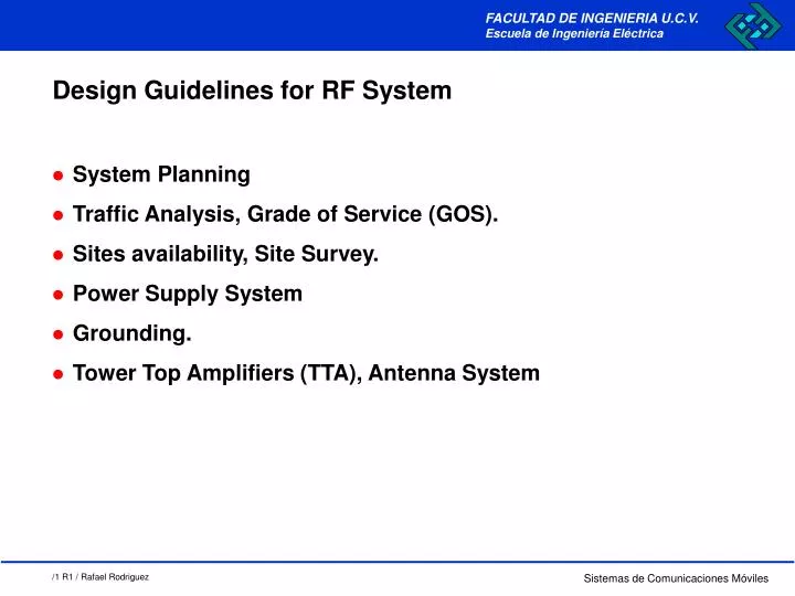
Design Guidelines for RF System. System Planning Traffic Analysis, Grade of Service (GOS). Sites availability, Site Survey. Power Supply System Grounding. Tower Top Amplifiers (TTA), Antenna System. Funciones del Sistema de Alimentación Correción de caidas de tensión

E N D
Design Guidelines for RF System • System Planning • Traffic Analysis, Grade of Service (GOS). • Sites availability, Site Survey. • Power Supply System • Grounding. • Tower Top Amplifiers (TTA), Antenna System
Funciones del Sistema de Alimentación Correción de caidas de tensión Atenuación de picos de tensión Atenuación de ruido Suministro de energía como fuente de emergencia Satisfacción de demandas de corriente superiores a la capacidad de los equipos Suministro programado de energía Power Supply System
Power Supply System PANEL DE BREAKERS RECTIFICADORES CONTROL COMUN CONVERTIDOR BATERIAS INVERSOR BATERIAS
Convertidor AC-DC (Rectificador) Convertidor AC-AC Convertidor DC-DC Convertidor DC-AC (Inversor) Power Supply System
Power Supply System SERVICIO EN PARALELO SERVICIO CON RECTIFICADORES RED RED Rectificador Rectificador IB IL Baterias CARGA D.C. CARGA D.C.
IREC IL IB RED Rectificador Carga D.C. Baterias Power Supply System VAC VDC Vflotacion Ta IRCmaxima = ILIM Icarga I bateria I flotacion Perdida ILIM - Icarga Retorno
Power Supply System • Evolución Historica de los Rectificadores • CONVERTIDORES ROTATIVOS • RECTIFICADORES FERRORESONANTES • RECTIFICADOR POR AMPLIFICACION MAGNETICA • Alta Confiabilidad, Ineficientes, Grandes Dimensiones • RECTIFICADOR CONTROLADO POR SCR • Relativa confiabilidad • RECTIFICADOR FERRORESONANTE CONTROLADO • Alta confiabilidad, Magnetico + SCR • RECTIFICADOR DE ALTA FRECUENCIA • Tamaño reducido, Sofisticados y Delicados (140/160 KHz)
IREC IL IB RED Rectificador CARGA D.C. Baterias Power Supply System RECTIFICADOR - CARGADOR CALCULO DE CAPACIDAD IREC = IL + 1.10 * (IL* TA / TR) (Pb) IREC = IL + 1.40 * (IL* TA / TR) (Ni Cd)
I1 I2 IT CARGA D.C. In Baterias Power Supply System RECTIFICADOR - CARGADOR CONEXIONES REDUNDANTES “HOT STAND BY” Capacidad Individual = IT (MAX) / (n-1)
I1 I2 IT CARGA D.C. In Baterias Power Supply System RECTIFICADOR - CARGADOR CONEXIONES REDUNDANTES “(n + 1)” Capacidad Individual = IT = I1 = I2 = I(n+1)