Download
1 / 25
250 likes | 428 Views
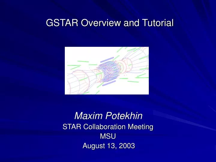
GSTAR Overview and Tutorial. Maxim Potekhin STAR Collaboration Meeting MSU August 13, 2003. Goals of this presentation. provide a quick intro to GSTAR increase the user awareness of this simple-to-use simulation tool illustrate the mechanism of geometry definition

E N D
GSTAR Overview and Tutorial Maxim Potekhin STAR Collaboration Meeting MSU August 13, 2003
Goals of this presentation • provide a quick intro to GSTAR • increase the user awareness of this simple-to-use simulation tool • illustrate the mechanism of geometry definition • show how a simple ad hoc simulation can be run by the user, and how to modify and rebuild the geometry • encourage the community participation in the geometry maintenance and future development of the STAR Detector Description Services
Overview • The concept of GSTAR • Example of a simple GSTAR session • Geometry definition and versioning • How to modify and reload the geometry • Event input • Event and geometry output • Useful commands for geometry visualization and testing
GSTAR (a.k.a. staf) • GSTAR foundation: standard CERN software such as PAW and GEANT 3.21, with manipulation of underlying ZEBRA banks. • GSTAR user interface: based on KUIP. Allows both interactive mode and full scripting (KUMAC files). Supports commands for interactive GEANT and PAW, plus ZEBRA debugging tools. • The not-so-standard GSTAR component: the Detector Geometry Description (distinct from the GSTAR core but interfacing it) • The core design idea: instrument the GEANT code in a way that allows for dynamic loading of most functions. This gives the developer and users much flexibility in enhancing the functionality without rebuilding the executable, and provides for the code modularity
GSTAR • Practical benefits: • a versatile platform, the workhorse of the STAR simulations • interactive detector exploration tool, friendly UI • advanced scripting based on standard KUIP • standardized output format – integration with the reco chain • a few standard input formats – integration with the event generators • useful help pages system • the ease of dynamic loading of user-created and/or user-modified functions (rebuilding on-the-fly) • enhanced interface to the GEANT debugging tools • geometry persistent in the output
GSTAR components • The GSTAR executable • named “staf” for historical reasons, resides in $STAF/bin • The geometry DLL – compiled from source files located in • $STAR/pams/geometry (more on the geometry description later) • Makefiles (used implicitly when running certain commands in GSTAR) • The i/o module handling a variety of event data formats • KUMAC files • Optional user DLL’s that can be built and loaded virtually at any time
Starting a GSTAR session With the standard STAR environment: ~/myworkdir> staf –w 1 where “1” will open a standard X11 graphics window, and “0” can be used for sessions without the need for graphics (obviously comes from PAW). This gets you to a prompt: staf> Alternatively, one can run in batch mode: ~/myworkdir> staf –w 0 –b myscript.kumac
A simple GSTAR session: detector visualization staf> detp geometry year2003 staf> make geometry staf> draw CAVE staf> dcut CAVE z 0.1 10 10 0.02 0.02
Getting help: an example staf > man dcut Command "/GEANT/DRAWING/DCUT" : * GEANT/DRAWING/DCUT NAME CAXIS CUTVAL [ U0 V0 SU SV ] NAME C 'Volume name' CAXIS C 'Axis value' CUTVAL R 'Cut plane distance from the origin along the axis' U0 R 'U-coord. (horizontal) of volume origin' V0 R 'V-coord. (vertical) of volume origin' SU R 'Scale factor for U-coord.' SV R 'Scale factor for V-coord.' Possible CAXIS values are: X Y Z CALL GDRAWC(name,iaxis,cutval,u0,v0,su,sv) The cut plane is normal to caxis (X,Y,Z), corresponding to iaxis (1,2,3), and placed at the distance cutval from the origin. The resulting picture is seen from the the same axis. If optional parameters are missing, the current values in /GCDRAW/ are taken. When HIDE Mode is ON, it is possible to get the same effect with the CVOL/BOX command.
Detector Geometry Description • Number of detector subsystems : 19 (not all necessarily included in a particular configuration) • Custom macro “geometry language” (*.g files) • based on the obscure Fortran preprocessor called Mortran • ideally suited for application-specific Fortran code structuring • in many cases, helps circumvent limitations of Fortran • can be of help with the GEANT learning curve • has been successfully used in a number of projects • 11+ k lines of geometry code, largely user maintained • volume numbering maps (not part of the geometry per se) are maintained separately in “g2t” files. • Difficult to version and maintain.
Detector Geometry Description [rcas6027] ~/> ls $STAR/pams/geometry/ bbcmgeo/ calbgeo/ fpdmgeo/ geometry/ magpgeo/ phmdgeo/ supogeo/ tpcegeo/ vpddgeo/ btofgeo/ cavegeo/ ecalgeo/ ftpcgeo/ mfldgeo/ pipegeo/ richgeo/ svttgeo/ upstgeo/ zcalgeo/
Detector Geometry Description • Code example: Block SVTT is the mother of all SVT volumes * Material Air Attribute SVTT seen=0 colo=1 Shape TUBE Rmin=svtg_RsizeMin, Rmax=svtg_RsizeMax, dz=svtg_ZsizeMax * End rings to support the ladders: * Create SIRP " inner end ring polygon piece " Position SIRP Z=serg_EndRngZm+serg_EndRngTh/2 AlphaZ=22.5
Detector Geometry Versioning • STAR Geometry Versioning: the steering file:$STAR/pams/geometry/geometry/geometry.g • contains the complete history of the STAR configurations • calls the constructors of individual detector subsystems and sets some of their parameters • versioning is done at run time based on the value of “geometry” parameter. Example: detp geometry year2003 • The detp command allows the user to set certain predefined configuration parameters: Configurations : year_1a,s,b,h,c;year_2a, year2000, year2001, year2002, year2003 Gcalor : Gcalor_on, Gcalor_off Geant Physics : Hadr_on, Hadr_off (GHEISHA) Geant Physics : Phys_off, Decay_Only Geometry Detail : mwc_off, pse_off, 4th_off Magnetic Field : Field_on/off, field=value Auxillary keys : Debug_on/off • The detp command also allows the user to set some variables (structure elements) prior to building the geometry, thus facilitating experimentation and debugging
Detector Geometry Versioning on YEAR2003 { draft 2003 geometry - TPC+CTB+FTPC+CaloPatch2+SVT3+BBC+FPD+ECAL; "svt: 3 layers "; nsi=6 " 3 bi-plane layers, nsi<=7 "; wfr=0 " numebring is in the code "; wdm=0 " width is in the code "; "tpc: standard, i.e. " mwc=on " Multiwire chambers are read-out "; pse=on " inner sector has pseudo padrows "; "ctb: central trigger barrer "; Itof=2 " btofgeo2 "; btofconfig=5; "calb" ems=on "endcap " nmod={60,0}; shift={0,0}; " 60 sectors " "ecal" ecal_config=1 "one ecal patch, west " ecal_fill=1 " sectors 2-5 filled " "beam-beam counter " bbcm=on "forward pion detector " fpdm=on "field version " Mf=4; "tabulated field, with correction " "geometry correction " CorrNum = 0; }
Building geometry during a GSTAR session staf> detp geometry year2003 • The version tag is set, which will select the requisite GEANT configuration and parameters at run time. staf> make geometry • The “make” utility is invoked, which will keep track of any geometry source code that might be present in the pams/geometry path in the working directory. staf> gclose all • Closes the Zebra banks, calculates various GEANT cross-sections staf> * make some drawings or trigger events here • Do something useful here • .......................................... • ..........................................
“Hacking” the geometry Check out (cvs co) and edit any of the files in the pams/geometry path in the working directory, as desired. The “make” command will take care of the dependencies. staf> detp geometry year2003 • Choose the base geometry with which to work staf> make geometry • Build the GEANT geometry which will now include your changes staf> gclose all • Get ready for the simulation staf> * make some drawings or trigger events here • Do something useful here • .......................................... • .......................................... staf> gdrop all • Drop the Zebra banks, get ready for rebuilding geometry staf> * • If needed, modify the geometry source and repeat the cycle
Debugging the geometry Display the GEANT volume hierarchy • dtree ECAL
Subsystem visualization • next • draw ECAL • next • draw SVTT 40 30 120 10 10 0.18 0.18
Event visualization • detp geometry year2003 • make geometry • gclose all • debug on enable track visualization: • switch 2 3 • switch 4 3 produce a view of the detector • dcut CAVE z 0.1 10 10 0.02 0.02 select one electron track per event: • gkine 1 3 0.2 0.2 0.5 0.5 • trig observe the hits: • dhits
Persisting GEANT geometry and output This simple command during the session will open an output file: • gfile o my_file.fz After that, subsequent events shall be recorded in the file. The geometry will also be persisted in a transparent manner. A neat exercise: define a geometry, create a few events with kinematic tracks, save them in a file, then quit GSTAR. Reopen the file in a fresh GSTAR/staf session using the command: • gfile p my_file.fz And inspect the geometry using the command discussed above. Also, issue triggers and use the dhits command to look at the hits.
Using external input from event generators First, load the module responsible for handling the various formats of input files, • make gstar then open a file with event data: • us/input please my_event_file.nt After that, subsequent events can be read from the file, and propagated in GEANT, with each “trig” command. Naturally, this can be combined with opening an output file and recording the simulated GEANT event data. The following command, issued after propagating a Hijing event, produced the hits picture on the right: • dhits
Event diagnostics The following commands are useful in inspecting the GEANT event’s contents: • gprint kine prints the contents of the event particle table (tracks) • gprint vert prints vertices info, such as positions and generated track numbers • gprint hits prints GEANT “hits” as recorded in various detector elements, hits also can be inspected in individual detector subsystems: • gprint hits ecal ====> HITS IN DETECTOR ** ESCI ** OF SET ** ECAH ** <==== HITS TRACK ECVO EMOD ESEC EMGT EPER ETAR BIRK 1 377 2 4 1 3 1 7 2.482E-03 2 276 2 2 1 16 1 6 1.160E-03 3 248 1 5 2 1 5 2 1.646E-03 4 248 1 5 3 1 5 2 2.072E-04 5 248 1 5 3 1 5 3 1.308E-03
Triggers and scalers When studying efficiencies of rare signal triggers, we want to save considerable computational resources by pre-selecting events according to some basic trigger criteria, avoiding the costly propagation and reconstruction of uninteresting events. One recent example: the study of J/Psi and Upsilon trigger based on calorimeter hits. A new feature has been implemented that includes: • A template for the event selection logic • Augmented event header structure which carries the running scaler for rejected events, allowing the user to correctly calculate the normalization factors. • The “g2t” interface with reconstruction for transparent access to such data in root files. How to do that: • Write the “AGUDIGI” subroutine called automatically by GEANT at the hits digitization stage • Use any of the methods available to check for the trigger condition such as number of hits in a particular detector subsystem • Set the IEOTRI flag (standard GEANT) according to the event selection criteria. Rejected events will then be completely ignored and won’t be present in the output stream.
subroutine AGUDIGI call hepevnt() call ecal_trigger() return end * subroutine ECAL_TRIGGER() +CDE,GCBANK,GCUNIT,SCLINK *KEEP,GCFLAG. COMMON/GCFLAG/IDEBUG,IDEMIN,IDEMAX,ITEST,IDRUN,IDEVT,IEORUN + ,IEOTRI,IEVENT,ISWIT(10),IFINIT(20),NEVENT,NRNDM(2) * COMMON/HTCHK/ CLHTS INTEGER CLHTS integer NUM(3) /1,1,1/ integer NREJECT/0/ integer LEN/7/, REJ_OFFSET/7/ integer ia, L * make the event "bad" by default: IEOTRI=1; call hit_check('CALH','CSUP') if(CLHTS.eq.2) IEOTRI=0 call hit_check('CALH','CSDA') if(CLHTS.eq.2) IEOTRI=0 call hit_check('ECAH','ESCI') if(CLHTS.eq.2) IEOTRI=0 call hit_check('ECAH','EHMS') if(CLHTS.eq.2) IEOTRI=0 if(IEOTRI.eq.0) then call REBANK('/EVNT/PASS/MPAR',NUM,-LEN,L,ia) if (L>0) IQ(L+REJ_OFFSET+2)=NREJECT NREJECT=0 else NREJECT=NREJECT+1 endif return end Triggers and scalers: a code example
The GSTAR Web page Please visit the GSTAR Web page: http://www.star.bnl.gov/STAR/comp/simu/gstar/gstar.html for more information on the topics presented here